MagicBus gave me an idea. How about using allpass filter center frequency the Nyquist. Then all the images will shifted 180° and subtract from the signal.
I'll be following with interest although your approach is beyond my understanding. The way I did - or did I?- is with an active circuit working in the analog domain, no software involved. I put it aside until I have the means to measure it properly. But I will start a thread FWIW...
It needs to make a point where I reached in this research.

The I₂S first enters a shift register 2×64 bit to provide 4 samples of data.
Two high quality DACs tied their current outputs feed an integrator to output ramped (linear interpolated) but untouched sampled points. An analog spline cubic interpolator made of four low cost DACs TDA1387 and additioners and multipliers as AD633 bring a additive signal to the integrator and shapes the signals to perfection always keeping as sacred, untouched, the sampled points. Where goes wrong is above 10khz. The source digital signal is delivered modulated as radio RF reception. Besides the signal it contains its upper side band issue from the AM modulation with the sampling rate.
Now the technology is in RF domain. The DAC raw signal first is demodulated by heterodyne And I get very clean signal but frequency inverted 20khz becomes 2.7khz, 10khz becomes 12.7khz, 1khz becomes 21.7khz. All I now need is to remodulated this clean signal back but only in single side band the lower side band, and compliment the perfect signal above 10khz to 20khz.
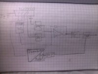
There are two methods to modulate in SSB, the Hartley and the Weaver. The Weaver is most realistic but too complicated, the Hartley looks simple,

but the quadrature phase shifter is done digitally applying Hilbert's transform. Last night I found this passive circuit


From this website https://cr4.globalspec.com/thread/98785/Frequency-Independent-Phase-Shifter. I will try it out today.
The I₂S first enters a shift register 2×64 bit to provide 4 samples of data.
Two high quality DACs tied their current outputs feed an integrator to output ramped (linear interpolated) but untouched sampled points. An analog spline cubic interpolator made of four low cost DACs TDA1387 and additioners and multipliers as AD633 bring a additive signal to the integrator and shapes the signals to perfection always keeping as sacred, untouched, the sampled points. Where goes wrong is above 10khz. The source digital signal is delivered modulated as radio RF reception. Besides the signal it contains its upper side band issue from the AM modulation with the sampling rate.
Now the technology is in RF domain. The DAC raw signal first is demodulated by heterodyne And I get very clean signal but frequency inverted 20khz becomes 2.7khz, 10khz becomes 12.7khz, 1khz becomes 21.7khz. All I now need is to remodulated this clean signal back but only in single side band the lower side band, and compliment the perfect signal above 10khz to 20khz.
There are two methods to modulate in SSB, the Hartley and the Weaver. The Weaver is most realistic but too complicated, the Hartley looks simple,
but the quadrature phase shifter is done digitally applying Hilbert's transform. Last night I found this passive circuit
From this website https://cr4.globalspec.com/thread/98785/Frequency-Independent-Phase-Shifter. I will try it out today.
Attachments
I found more information about the quadrant phase shifter.
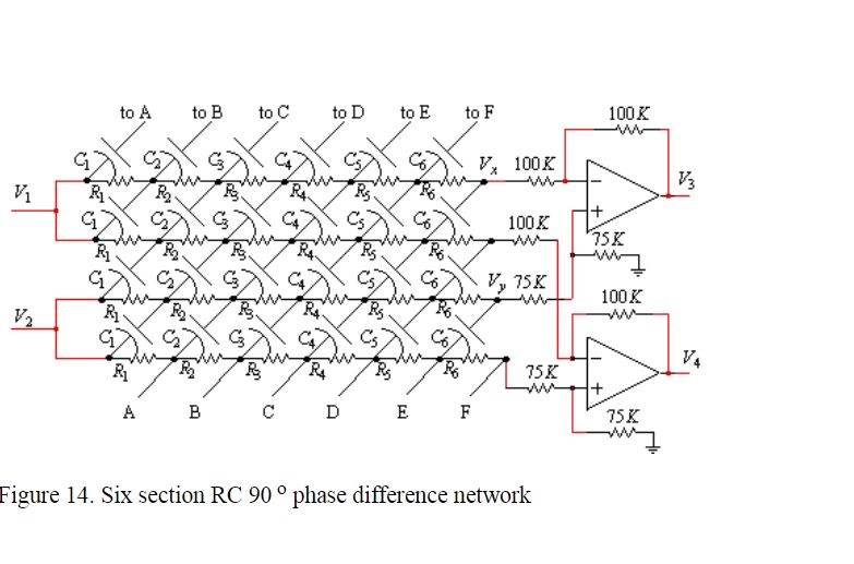
This filter is rather difficult to calculate as it uses Jacobi Elliptic function, but the author has provided a matlab script (posted bellow) to calculate everything.
As most intellectual work is done, I wanted to start realizing the decided parts.
The DACs
This circuit needs numerous DACs that their noise will add up. The TDA1387 is nice but 98db S/N, minimum six such DACs used and the result becomes shabby. So looked around and decided to use the PCM1794. This DAC can function as NOS mono 24bit DAC 132db, it can have independent clock to eliminate jitter, It can provide me two positive outputs and two negative outputs in current that I need for arithmetic operations and I need only 4 units per channel. The price is not very high as was a few years ago and buying by ten will be still cheaper.
The problem with the DAC in NOS mode, it needs right justified format. To have fixed word length phase shifts for 16/24 bit input data, I need to convert the multiplexed I₂S into two independent constant 32bit length right justified serial data. A new task.
Attachments
Last edited:
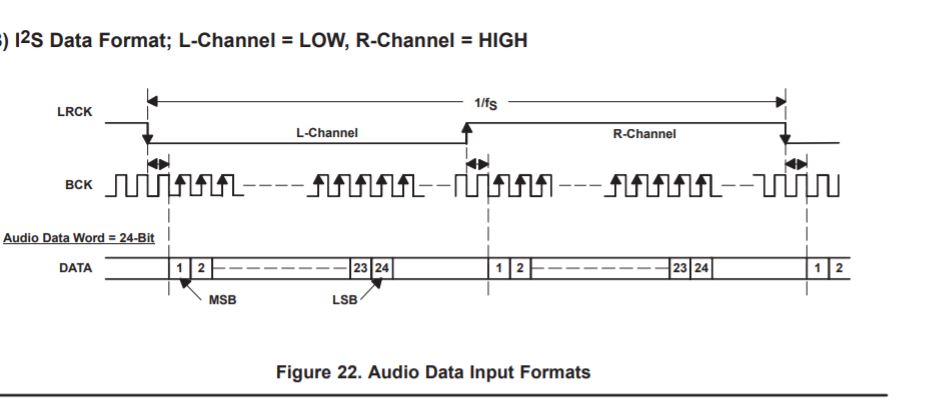
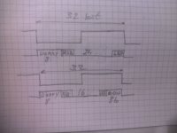
To convert the I2S into right justified required by the DAC need the respect the following timing.
This is the initial I2S format.
The forma required is this.

In addition, in order to keep the same delay of samples, I want in both 16 and 24bit, 32bit word lenght.
This is the expected result.

The first 8bits are dummy only to make a total of 32bits. With 24bit it is straight forward, but with 16bit the last 8 bits must be 0 to keep the low byte inactive.
This is the initial I2S format.
The forma required is this.
In addition, in order to keep the same delay of samples, I want in both 16 and 24bit, 32bit word lenght.
This is the expected result.
The first 8bits are dummy only to make a total of 32bits. With 24bit it is straight forward, but with 16bit the last 8 bits must be 0 to keep the low byte inactive.
Attachments

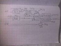
This is the starting circuit.


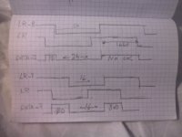
In order to fill 8 dummy bits the data is delayed 7 clocks as I2S has 1 allready delayed. The LR is delayed by 8 bits. To bring the L channel data in phase with the the R, the data needs to be delayed 24 or 16 ck selected by BR. If the WL is 24, then at the end of the word indicated by the delayed LR-8 until the fall of LR that is 24-8=16ck the output clock is stopped, to become 32bit instead of 48. If the WL is 16, then the LR-8 to fall ofLR is 16-8=8ck the multiplex fills the data with 8×0.
Will the WL 24/16 is manual or automatic, I will look at at later.
Attachments
Last edited:
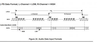
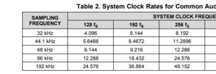
I am trying to understand about the clock of the DAC. The datasheet says it must be synchronous with WRCK but at what frequency. The datasheet shows the WRCK noted to have a duration of 1/4fs to 1/8fs.
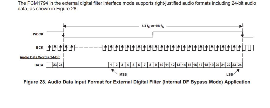
What does this means.
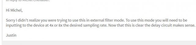
On TI forum I found a TI expert saying.

Can someone explain to me what frequency clock I must supply.
Second question.
Is there any synchronous PLL oscillator chips?
What does this means.
On TI forum I found a TI expert saying.
Can someone explain to me what frequency clock I must supply.
Second question.
Is there any synchronous PLL oscillator chips?
Attachments
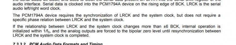
By reading more in details, I read the following.

Does this means the SCK must be equal to LRCK but it can allow a jitter relative variation of +/-6 clocks?
I will use the PLL 74HCT4046 to generate the SCK, maybe I can extract automatic 24/16 bit mode as only 24bit uses 96kfs.
Does this means the SCK must be equal to LRCK but it can allow a jitter relative variation of +/-6 clocks?
I will use the PLL 74HCT4046 to generate the SCK, maybe I can extract automatic 24/16 bit mode as only 24bit uses 96kfs.
Attachments
Last edited:
If I look what Nfs in the document means, then 4fs or 8fs means the SCK must be 4 or 8 times the WRCK. That is for 96kfs the SCK must be 4×96 or 8×96khz.
It does make sense, the SCK here is used only to pass from FIFO buffer to output at word rate not at BCK.
In other words my PLL must output 8 times faster clock than the LRCK for 44.1k and 44k and 4 times for 96k.
It does make sense, the SCK here is used only to pass from FIFO buffer to output at word rate not at BCK.
In other words my PLL must output 8 times faster clock than the LRCK for 44.1k and 44k and 4 times for 96k.
Attachments
Why do you look into these interfacing matters instead of first checking by simulation whether the concept of post #44 works at all? If it doesn't, you also don't need to solve the interfacing issue.
In post 40 I show the 20khz recreated by Weaver modulator, it works. With Hartley it is better on transient as it filters on higher frequency and only once. The quadrature phase splitter filter in post 44 is used in many SSB radio applications and this in the range of 2 decades as 200hz to 4khz, when I need only 10k to 20k. So I am full confident that I can realize it. If I stopped, is for two reasons. One I will be dealing with simulation troubles passing my efforts by fighting with LTspice . Second, I am afraid it works too well and I will be tempted, which will happen in near future no doubt, to treat the whole audio spectrum 20hz to 20khz by Hartley modulator, then, I am totally off track from this project. In fact I am developing it at the background at lower pace.
This why I decided to start concretize first what has already finished projecting.
This why I decided to start concretize first what has already finished projecting.
Last edited:
I found more information about the quadrant phase shifter.
This filter is rather difficult to calculate as it uses Jacobi Elliptic function, but the author has provided a matlab script (posted bellow) to calculate everything.
As most intellectual work is done, I wanted to start realizing the decided parts.
The DACs
This circuit needs numerous DACs that their noise will add up. The TDA1387 is nice but 98db S/N, minimum six such DACs used and the result becomes shabby. So looked around and decided to use the PCM1794. This DAC can function as NOS mono 24bit DAC 132db, it can have independent clock to eliminate jitter, It can provide me two positive outputs and two negative outputs in current that I need for arithmetic operations and I need only 4 units per channel. The price is not very high as was a few years ago and buying by ten will be still cheaper.
The problem with the DAC in NOS mode, it needs right justified format. To have fixed word length phase shifts for 16/24 bit input data, I need to convert the multiplexed I₂S into two independent constant 32bit length right justified serial data. A new task.
I'm pretty sure the JLsounds USB bridge can OP the required format to run these DACs in mono mode sans digital filter.
I'm still at a loss as to what you are actually trying to achieve here.
TCD
I'm also uncertain. They seem to be attempting to design a circuit which will perform interpolation of a digital signal but directly in the continuous-time domain. If this is so, I'm not sure what the proposed advantages are over digital interpolation+low-pass analog (final) reconstruction filter?
Is it this? http://www.jlsounds.com/uploads/I2SoverUSB v.III.pdf
It converts USB to I2S and variant types only. The PCM1794 is fix 24bit right justified. The datasheet says it accepts 16 and 20bit formats, but it doesn't place the MSB where it should and output level goes low, this what I learned from the TI forum. The new DSD1794 can be programed manually for word length. This why I must make special circuit to fill the 8 lower bits by zeros for 16bit format. Another problem is the shift register. To have the same one for 16&24bit, I must reduce the 48bit word length to 32bit when running at 24bit format, for that I must stop the clock 16beats once the 32bit data got sent.
A FPGA or a microcontroller can also do all this.
The purpose of the DAC, is to convert with the highest precision possible in time domain, in contrast to digital versions which are in frequency domain.
Last edited:
Is it this? http://www.jlsounds.com/uploads/I2SoverUSB v.III.pdf
It converts USB to I2S and variant types only. The PCM1794 is fix 24bit right justified. The datasheet says it accepts 16 and 20bit formats, but it doesn't place the MSB where it should and output level goes low, this what I learned from the TI forum. The new DSD1794 can be programed manually for word length. This why I must make special circuit to fill the 8 lower bits by zeros for 16bit format. Another problem is the shift register. To have the same one for 16&24bit, I must reduce the 48bit word length to 32bit when running at 24bit format, for that I must stop the clock 16beats once the 32bit data got sent.
A FPGA or a microcontroller can also do all this.
The purpose of the DAC, is to convert with the highest precision possible in time domain, in contrast to digital versions which are in frequency domain.
I think you need to re read the data sheet, sorry I'm too busy ATM.
I've had PCM1704 running NOS connected directly to JLsounds board and I'm
fairly certain they require the same format. Happy to stand corrected if this is
not the case.
TCD
Is it this? http://www.jlsounds.com/uploads/I2SoverUSB v.III.pdf
It converts USB to I2S and variant types only. The PCM1794 is fix 24bit right justified. The datasheet says it accepts 16 and 20bit formats, but it doesn't place the MSB where it should and output level goes low, this what I learned from the TI forum. The new DSD1794 can be programed manually for word length. This why I must make special circuit to fill the 8 lower bits by zeros for 16bit format. Another problem is the shift register. To have the same one for 16&24bit, I must reduce the 48bit word length to 32bit when running at 24bit format, for that I must stop the clock 16beats once the 32bit data got sent.
A FPGA or a microcontroller can also do all this.
The purpose of the DAC, is to convert with the highest precision possible in time domain, in contrast to digital versions which are in frequency domain.
I would recommend trying to use some means to format convert from PCM to
DSD256 (HQplayer or other) then feed any number of DACs that can handle
native DSD (PCM1792 etc). They will already have inbuilt 'analog' low pass filter.
Would this satisfy your time domain requirements?
TCD
I'm also uncertain. They seem to be attempting to design a circuit which will perform interpolation of a digital signal but directly in the continuous-time domain. If this is so, I'm not sure what the proposed advantages are over digital interpolation+low-pass analog (final) reconstruction filter?
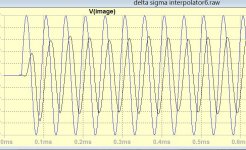
This is 20khz burst after the digital interpolation of very high quality DAC.
This is my way of using radio transmission technology for 20khz.
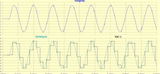
This is how my analog interpolator works at 8khz without any filtering. Notice that the sampled values are untouched.
This is 10khz after 1st order low pass (blue) ready to be complimented by radio up to 20khz.(black is the input of the ADC delayed.
Attachments

Last edited:
Can you post a frequency-domain depiction of the suppression of the interpolated signal's image bands?
This from post 39. It is the image signal of 20khz that I had the intention before to subtract from the main. The 20khz side band is just the opposite, It becomes high and the image low. The quadrant phase filter rank gives the attenuation of the image. Table1 on this website gives the relationship. Mixers in Communications
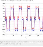
This image is from Stereophile review of streamer using PCM1794.
https://www.diyaudio.com/forums/attachment.php?attachmentid=912090&stc=1&d=1610758365
With my DAC, I would get clean sin wave.
Attachments
- Home
- Source & Line
- Digital Line Level
- Analog Delta-Sigma interpolation DAC