.
This was supposed to be a private project, and I was not planning to publish.
But it is amazing to see people still talking about the AD844 as IV.
That is even though Pedja has published a very similar but discrete circuit quite some 15 years ago.
https://www.diyaudio.com/archive/bl...-out-production-pedja-rogic-ddnf-iv-stage.pdf
The problem with the AD844 is that it lacks bias.
The -Vin node has a Zin of 50 ohm, which implies a bias of about 0.25mA.
Using a 0.25mA-biased push-pull input to convey (say) 1mA current signal can only mean that it has to work in Class AB,
i.e. no longer push-pull as long as signal is > -6dBFS.
And yes, you can improve this by stacking 4x or 8x AD844s.
But it is a clumsy and no-longer-elegant solution, apart from expensive.
Just for fun, we did something more similar to a discrete-but-simplified AD844 than Pedja’s.
It has a bias of 2mA, i.e. equal to 8x AD844 in parallel.
Performance is not comparable to the CEN IV, but it uses fixed rails and has an integrated emitter follower buffer.
Bandwidth & distortion were measured with 2mApp DAC current (e.g. PCM1704), and Riv is 2.8k for 2Vrms output.
For the likes of PCM1796, you can increase bias to 3mA and it will couple with 4mApp without much loss in performance.
For more DAC current, you will have to stack as well, or use through hole components for even higher bias.
We want to use SMD because you can get really-low-noise Toshiba dual BJTs that are easy obtainiums.
And they are monolithic, ie. perfect for thermal tracking.
A lot more fun than stacking AD844’s. 🙂
Patrick
.
Attachments
Very nice, how it compares vs the bulker discrete published by Pedja Rogic and made from 550C/560C bjt family please ? And vs an Opa 861 instead of the AD844 ?
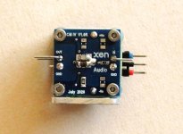
Thnak you for sharing, plus the tiny board is very handy 🙂
Thnak you for sharing, plus the tiny board is very handy 🙂
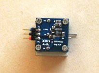
> What types of transistors did you use?
As mentioned in the article, low noise dual NPN and PNP from Toshiba, in SOT23-5.
> And what values for the other components?
Not obvious enough from the photo ? 🙂
> how it compares vs the bulker discrete published by Pedja Rogic and made from 550C/560C bjt family please ?
You can compare the THD plots at 1kHz 2Vrms output.
And the bandwidth figure (measured at 2Vrms) will give you a very good idea on the slew rate.
Cheers,
Patrick
>I have a feeling this design will sounds great
I am sure the one published by Pedja (linked in post #1) also, be it somewhat different.
A real shame that it does not get more attention.
The nice thing here is the thermal tracking and matching of the dual devices.
And I have lots of them left over from the discrete opamp project :
One Last Attempt at Discrete Opamp in DIP8 Footprint
🙂
Patrick
It is so simple that I am sure you can breadboard (or vero) this with through hole components in half an hour, for a first impression.
Just need some BC327/337 to start with.
😉
Patrick
Just need some BC327/337 to start with.
😉
Patrick
Thanks Patrick,
Very brillant to have also putted headroom enough for pps 1206 case...my modest tweaking experience showed me it is a game changer vs C0G...at least when the music is playing 🙂
Very brillant to have also putted headroom enough for pps 1206 case...my modest tweaking experience showed me it is a game changer vs C0G...at least when the music is playing 🙂
Yep PPS is better on the analog path 🙂...despite a bigger inductance due to the size. And now if low esr is not a problem, they exist in several uF...cool.
As in diamond layout the traces are crossing eachothers I assume one should use a 4 layers pcb for better result ?
As in diamond layout the traces are crossing eachothers I assume one should use a 4 layers pcb for better result ?
> What types of transistors did you use?
As mentioned in the article, low noise dual NPN and PNP from Toshiba, in SOT23-5.
And you want to keep the type numbers secret? I saw two BJT type numbers in the article, but I understood from the text that those are old types you don't use.
I surmise sorting out the smd replacment of the old bc550c/560c is a place to start...But itshould not be too hard to find some double low noise BJT ?
EUVL was solding the last CEN and SEN pcbs and sorted out smds...
EUVL was solding the last CEN and SEN pcbs and sorted out smds...
> And you want to keep the type numbers secret ?
Too many people here copy without asking. I learned my lessons.
But someone experienced like yourself should have no problems finding them at Mouser or Toshiba website.
You can PM me if you cannot find them. Which I doubt.
Cheers,
Patrick
Too many people here copy without asking. I learned my lessons.
But someone experienced like yourself should have no problems finding them at Mouser or Toshiba website.
You can PM me if you cannot find them. Which I doubt.
Cheers,
Patrick
BJT Matching
Someone asked how good was the BJT matching.
From the batch I ordered (100 each), there were almost no NPN to PNP match (for hfe).
NPN to NPN, or PNP to PNP are normally much less than 1%, though there are some exceptions.
NPN to PNP I used in the build was about 10~15% match.
But the measurement was almost identical to Spice simulations.
If your aim is lowest possible distortion, then it is important to match the two IV's used in balanced output.
This will cancel H2 by ~5x or better.
H3 is 8x below H2 in our example.
Patrick
Although it's a 10 posts thread, my memory said to me I AM the guy who asked about sorting out.
...input is just about suorting out the ids...while I have no idea... -no matched humor level-
...input is just about suorting out the ids...while I have no idea... -no matched humor level-
- Home
- Source & Line
- Digital Line Level
- A Simple Discrete Current-Mirror IV Converter, à la AD844