Thank you for your reply.Panasonic FC?
Hi grunfI'm glad to see tubes instead of op.amps, just keep going.
I used a similar scheme in my first DAC some fifteen years ago. Then I had two great mentors who were doctors for tubes in Croatia, unfortunately they are no longer with us today.
The first thing they objected to was the operating point ECC88 / 6N23P, with 1K in the cathode I ended up at 180R and a current over 10mA. This will be especially pronounced in SRPP junction without output buffer because SRPP itself is quite sensitive to the impedance of the next stage, in fact it should be calculated for a certain output impedance.
That's why I added an output buffer, simply cathode follower with ECC88. It was a big improvement. I played a bit with the tubes and in the end I chose the Ei ECC88 between 6N1P, 6N23P, Tesla PCC88 and Ei ECC88 which I still use today in the DAC in the output buffer.
For me, it was a big leap from op. amps and since then I haven't soldered a single op.amp on the signal path.
Finally, I enclose the scheme that I later used instead of SRPP, it is still a much better solution because you can go with a lower IV resistor and the sound itself was much better then SRPP.
Thanks for sharing your experience. Let's test the attached circuit.
Also, can the circuit diagram in the link below be directly applied to AD1862? It looks like a circuit that does I/V using a vacuum tube, so I'm interested.
https://www.diyaudio.com/community/threads/tube-i-v-stage.382184/#post-6954411
Hi guys!
I'm building my PSU2 at the moment.
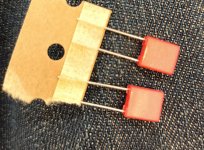
The WIMA 0.1 uF 100VDC capacitors disappeared from Mouser.
Mouser has so many other options .
Can I choose any of those?
I'm building my PSU2 at the moment.
The WIMA 0.1 uF 100VDC capacitors disappeared from Mouser.
Mouser has so many other options .
Can I choose any of those?
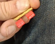
First option - 0.1/100 from list.Hi guys!
I'm building my PSU2 at the moment.
The WIMA 0.1 uF 100VDC capacitors disappeared from Mouser.
Mouser has so many other options .
Can I choose any of those?
Hey everyone,I need to settle down and just listen for a few days … first thing I noticed is the sound stage has improved.
PSU 1, LM 6171 , jlsounds, late 2012 Mac mini using jRiver player
Impressions to come
And thanks to those watching over me:
Miro, asilker and paddy and so many folks who I will never meet except of course online in this forum
Thanks everyone!
Must listen now…
I’m curious if any amount of burn in/ break in is necessary or recommended for Miro’s dac. I’ve only been using this dac for a couple hours and noticed some scratchy noise from both channels. I will have to listen more to provide more details.
Miro@intojazz There should be no scratchy noise. Can you try different opamp? (something in the DIP case)
Try it on headphones directly.
I only have soic opamps and no headphones. I will try with what I have
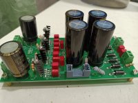
I'm almost finish the PSU-1. The problem is KG 4700uF. They are too big for place on board. I solder only two of them and the others don't fit
I want to solder Epcos B41851A5478M000 (4700/25) - they are smaller. Can I?
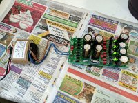
Unfortunately I could't found resistors from BOM but I have the alternative. That's why it wasn't so neat.
What I have left to do? - measure the voltage of PSU (+5 and +12) without DAC and then connect to DAC board and Amanero, right?
Oh, yes - one more thing - I was planning to build PSU 2 originally and solder J1-J13 2r2 resistors (2,2ohm). Can I use them or I need to change to jumpers? I could't found any LT's but everything was for PSU-1 so I buyed
What else to look out for?
Sorry for such many questions but it's my first diy Dac))
I want to solder Epcos B41851A5478M000 (4700/25) - they are smaller. Can I?
Unfortunately I could't found resistors from BOM but I have the alternative. That's why it wasn't so neat.
What I have left to do? - measure the voltage of PSU (+5 and +12) without DAC and then connect to DAC board and Amanero, right?
Oh, yes - one more thing - I was planning to build PSU 2 originally and solder J1-J13 2r2 resistors (2,2ohm). Can I use them or I need to change to jumpers? I could't found any LT's but everything was for PSU-1 so I buyed
What else to look out for?
Sorry for such many questions but it's my first diy Dac))
Attachments
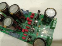
Is fitting the remaining 2 capacitors under the board an option? It will create the need for a taller chassis though.I'm almost finish the PSU-1. The problem is KG 4700uF. They are too big for place on board. I solder only two of them and the others don't fit
I want to solder Epcos B41851A5478M000 (4700/25) - they are smaller. Can I?
Unfortunately I could't found resistors from BOM but I have the alternative. That's why it wasn't so neat.
What I have left to do? - measure the voltage of PSU (+5 and +12) without DAC and then connect to DAC board and Amanero, right?
Oh, yes - one more thing - I was planning to build PSU 2 originally and solder J1-J13 2r2 resistors (2,2ohm). Can I use them or I need to change to jumpers? I could't found any LT's but everything was for PSU-1 so I buyed
What else to look out for?
Sorry for such many questions but it's my first diy Dac))
Yup , power up the PSU to measure the voltages before connecting to any other boards.
I would let the 2.2ohm remain if they have been soldered already. They are not needed if using PSU1 but they do not take away anything significant from the power supply if you leave them on the board. i have them on the board.
Just try 47 to 220 uF general purpose cap i.e. not low esr, and desolder the output 0,1 uF cap.
Problem being to find not too good esr to lowisch the impedance output, do not choose audio cap and not too much high voltage...16 V for instance. Here no silmic 2 or kz or even fm or fc...just try normal caps...the good esr caps on the dac pcb near the loads do the job.
Problem being to find not too good esr to lowisch the impedance output, do not choose audio cap and not too much high voltage...16 V for instance. Here no silmic 2 or kz or even fm or fc...just try normal caps...the good esr caps on the dac pcb near the loads do the job.
Last edited:
Which caps I should change? 0.1uf - that's Wima but they're located near transistors and near the input. There is no output caps. I don't understand this moment. And why is change needed? Can you tell me please?Just try 47 to 220 uF general purpose cap i.e. not low esr, and desolder the output 0,1 uF cap.
Problem being to find not too good esr to lowisch the impedance output, do not choose audio cap and not too much high voltage...16 V for instance. Here no silmic 2 or kz or even fm or fc...just try normal caps...the good esr caps on the dac pcb near the loads do the job.
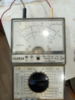
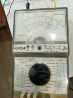
Guys, I just start the PSU. It's ok but the measures are little high. I'm attach a photos my voltmeter. Is it supposed to be like that?
Please look at photos. I can connect everything recently!
Please look at photos. I can connect everything recently!
Attachments
Yes, in the back connectors (+ -).13v for the 5v and 25v for the 12v? did you probe them at the correct points?
the ground is the reference. probe + and ground and then probe - and ground.Yes, in the back connectors (+ -).
Ground instead minus? For 5 and 12V?the ground is the reference. probe + and ground and then probe - and ground.
yes base on what you measured across + and - mentioned above, i expect that you will get around 5v and 12v, which will be correct.Ground instead minus? For 5 and 12V?
Ok. I will measure after work. Thanks!the ground is the reference. probe + and ground and then probe - and ground.
- Home
- Source & Line
- Digital Line Level
- DAC AD1862: Almost THT, I2S input, NOS, R-2R