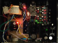
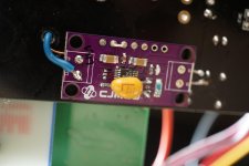
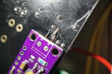
Do you have an idea where i could get the PCB from?
please PM me
@laserscrape
The Shunt on AVCC gave ma a more detailed and dynamic sound compared to my LT3042 Boards.
I am not sure if it is a matter of poor implementation of the LT3042 in my boards but I cannot hear any difference after replacing the LT1963 and AMS with LM317 and LT3042 for 1.2V and 3.3V.
I should be getting good regs. soon so will keep you updated if is worth upgrading the PSU for anything more than just I/V stage and AVCC.
...will keep you updated if is worth upgrading the PSU for anything more than just I/V stage and AVCC.
Rather different experience here. Local dedicated voltage regulators mounted on the dac board ground plane and located adjacent to the RF device needing power can help sound quality too, IME. In that respect, clocks and dac chips are often rather high frequency RF devices, sometimes operating somewhere between around 45MHz and 100MHz. Separate voltage regulator boards connected with hookup wire to RF device loads on a dac board should probably not be expected to work as well. I guess one takeaway from that is there can be more to think about than just the part number on a regulator chip in terms performance results. If separate regulator boards are the only choice, perhaps better to use a short-ish piece of RF coax cable rather than hookup wire to make the connection. If coax braid can be soldered to the board ground plane at each end, probably so much the better.
Last edited:
Mark, do you mean placing regulators close to RF device during board design?
Honestly I do not know how to place regulators other than the ones on an additional pcb.
I totally agree with you that long flying wires act like antennas collecting all RF and EMI garbage, in my board this is just an interim solution. The reg boards will be soldered to the pads where the AMS1117 was. I would need another reg than LT3042 as the current draw is too high there. I will use the LT3042 board I have to power the oscilator, and probably place it under the clock on the other side of the board.
exactly, it fits there nice. actually, I placed quite a few TH parts I changed at the opposite side, just because it was more convenient.... I will use the LT3042 board I have to power the oscilator, and probably place it under the clock on the other side of the board.
I mounted the local dedicated regulators on the bottom side of the ground plane, dead-bug style. Since the board I am using is only two layer, it was possible to safely drill some small holes for the regulator outputs to be routed directly up right near the power filter caps for each RF device.
That is correct, the trace is cut.and the leg connected is isolated from the original power trace?
It could but, in this way it will be easier to replace the capacitor.btw gnd could be soldered to the capacitors gnd pin just next.
Since we are talking about cap. I have hard that 3042 reg. does not perform well with the low esr oscon, that is there.
Does anyone has any experience in that matter? Should i replace it?
Dear all,
I stopped short of ripping / adding regulators and cutting traces to partition the channels since I want everything to still fit in the Breeze Audio Minishow0328 chassis.
Did a few things such as caps and 0.1uF MLCC bypasses around the OpAmps but so far my biggest bang for the buck has been to eliminate the 47uF round the OpAmps in favor of just 10uF 50V WIMAs.
- Status
- This old topic is closed. If you want to reopen this topic, contact a moderator using the "Report Post" button.
- Home
- Source & Line
- Digital Line Level
- China ES9018PRO ES9028PRO 9038PRO mods&upgrades


