Maybe worth checking out: PCB for Samuel Groner's low distortion passive notch filter ...particularly its good to visit Samuel Groner's website and take a look at the information there.
EDIT: regarding CBB film caps it also depends on the numbers that come after CBB: The difference between CBB capacitor and CL capacitor | Dongguan Xuanxuan Electrolytic Technology Co,.ltd
EDIT 2: I would suggest changing opamps to OPA1612. One could also try bypassing the opamps with film caps.
EDIT 3: Regarding resistor linearity: https://linearaudio.net/sites/linearaudio.net/files/CB-to-ES-V1-ref-3-IMG_0003.pdf
Last edited:
kozard,
One question for you, what procedure are you using to adjust the filter? The 2nd harmonic level is sensitive the the feedback pot adjustment, so just checking to make sure that's not a problem.
One question for you, what procedure are you using to adjust the filter? The 2nd harmonic level is sensitive the the feedback pot adjustment, so just checking to make sure that's not a problem.
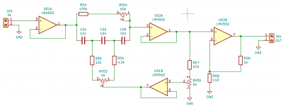
Right now I have assembled the first schematic (passive, no op-amps). So far I have not assembled the second schematic (active, shown with LM4562 in schematic).
I want to get the passive version and the passive components right before building the active version. Otherwise I suspect it will be too difficult to debug the active version.
I expect the CBB capacitors are metalized based upon the price but it was not specified. 99% sure they are not foil. They are not marked with the type.
I was reading here #118 about resistor distortion and I thought I might try building another passive one with the 1/4W 1% metal film replaced with 1W 1% metal film as an experiment. If they fit my machine pin headers I might try sockets for the capacitors so that I can try with both types of film capacitors that I have.
Attachments

Driving right now is what is inside the Digidesign 003:
The notch is about 50 dB to make the measurement task more suitable for the CS5361 ADC and the stock NE5532 in front of it.
Later I will upgrade the ADC op-amps with either OPA2132 or OPA1612. (I have a few OPA1612 on the way.) Right now I am working on the DAC after having first worked on improving the clocks/jitter.
- Channel 5: NE5532 (Stock) filter after the CS4392.
- Channel 6: OPA2132 (Modified) filter after the CS4392.
- Later (when they arrived) another channel will get OPA1612 as a test.
The notch is about 50 dB to make the measurement task more suitable for the CS5361 ADC and the stock NE5532 in front of it.
Later I will upgrade the ADC op-amps with either OPA2132 or OPA1612. (I have a few OPA1612 on the way.) Right now I am working on the DAC after having first worked on improving the clocks/jitter.
Last edited:
Okay, then you will need to find a calibration factor for each harmonic, since they will be partially attenuated by the notch skirts. Running pink noise through the filter may be a way to calibrate its amplitude response at each harmonic frequency.
I did calibrate by measuring the notch filter and using that as a mic calibration file in REW as suggested by the REW software author JohnPM: Howto - Distortion Measurements with REW
To be more specific what I did was:
To be more specific what I did was:
- Measured the notch filter three times without a cal file.
- Made a cal file with the notch filter measurement.
- Measured the DAC to ADC loop-back with the notch calibration file.
- Removed the calibration file.
- Remeasured the notch filter three times without a cal file.
- Plotted an overlay of the six notch filter measurements to verify no drift of the notch filter.
Last edited:
Quick question: In filters which harmonics are created and which harmonics are not created by the non-itineraries of polyester capacitors, polypropylene capacitors and metal film resistors? Which harmonics are absent and which are created?
Dunno. They are voltage dependent. Since there is no DC bias on them I would imagine mostly odd harmonics.
On the es9038q2m PCB labelled SMP, CB (the suggested one we are using)
I see a DC in without the voltage labelled at the front of the device
and then a jack with +15V,0V,-15V
and 0V,5V inputs
-Which ones are DC? Which ones are AC?
-Do some of the inputs accept both AC and DC?
-Or a range of voltages?
-What is the ideal arrangement powering the board?
It looks like it has a balanced ACc input, an unbalanced AC input then a DC input. Do I use all of them?
Thanks a lot,
Philip
Last edited:
The default is +/-15V (well regulated) DC where the PCB is labeled "-15 GND +15". Not AC! The recommended board is not AC. There is no rectifier nor filter capacitors on the recommended board.
The board has regulators and will generate the lower voltages from the +15.
Later on once you get started with the board you may read about the various voltages needed by the ES9038Q2M and how to improve the noise/quality of those supplies beyond that offered by the supplied 7805 and AMS1117 type regulators. This board (in my opinion) requires at least a real I/V output stage and low noise power supply upgrades. It is not a plug and play board (in my opinion). It is a project that requires substantial upgrades and investment.
Last edited:
Confised about power supply needs of the SMP CB es
I didnt understand part of this post.
The board has a +15v input, a GND, and -15v input.
How am I supposed to configure the 4 outputs of the LT board if they go into the 3 inputs on the board.
I thought that input was AC and the output of the LT board is DC...
There is another DC input on the front, What is that???
Thanks,
-Philip
Philip,
I recommend to use an R-core with two separate 18v (or maybe 15v) windings and two separate 9v windings (no center-tapped windings).
Also, for +-15v (or +-11v) supplies I recommend dual LT1083 power supplies like these: LT1083 Adjustable HIFI Linear Regulated Power Supply Board Dual Output | eBay
...Since LT1083 is a positive regulator only and because the two regulators on the above power supply boards do not share a common ground, I can use one regulator sort of upside down to regulate the -15v rail too. In that case the + output goes to ground on dac board, and the - output goes to the -15v rail on the dac board. I run a separate ground wire from each regulator to the dac board.
For a separate 5v (or 3.3v) supply I have been using an LT3042 board like: Low Noise LT3042 Linear Regulator Power Supply Board DC Converter Overvoltage | eBay ...Or, like: Dual Output LT3042 Ultra-Low Noise Linear Regulated Power Supply | eBay ...The regulator output voltages are set with a small SMD resistor. The seller normally can provide the output voltage you need, or you can change it later by changing the resistor.
The 5v supplies run from the 9v transformer windings.
There is a way of using a single supply (it involves J6 and the front jack). I don't recommend that.
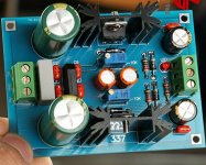
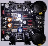
A simple beginner starting point is to use an LM317/LM337 type supply. The attached pictures show a couple of possibilities that work well and are easy to start with. The second one is low noise.
A simple beginner starting point is to use an LM317/LM337 type supply. The attached pictures show a couple of possibilities that work well and are easy to start with. The second one is low noise.
Attachments
ESS9038Q2M power supply confusion
I found Mark4w's answer to my previous question which I didn't quite understand and here are my more specific questions to help me clear things up.
It looks like the board has a balanced AC input 15V,GND,15V, another GND,5V on the same set of terminalsAC input and a DC input jack on the front without a voltage label.
The LT board outputs DC and it has 4 output terminals, 2 positive and 2 negative. How does that work when the PCB only has 3 inputs labelled +15V,GND,-15v?
is the GND,5V input DC as well?
What about the DC input jack on the front of the board?
Philip,
I recommend to use an R-core with two separate 18v (or maybe 15v) windings and two separate 9v windings (no center-tapped windings).
Also, for +-15v (or +-11v) supplies I recommend dual LT1083 power supplies like these: LT1083 Adjustable HIFI Linear Regulated Power Supply Board Dual Output | eBay
...Since LT1083 is a positive regulator only and because the two regulators on the above power supply boards do not share a common ground, I can use one regulator sort of upside down to regulate the -15v rail too. In that case the + output goes to ground on dac board, and the - output goes to the -15v rail on the dac board. I run a separate ground wire from each regulator to the dac board.
For a separate 5v (or 3.3v) supply I have been using an LT3042 board like: Low Noise LT3042 Linear Regulator Power Supply Board DC Converter Overvoltage | eBay ...Or, like: Dual Output LT3042 Ultra-Low Noise Linear Regulated Power Supply | eBay ...The regulator output voltages are set with a small SMD resistor. The seller normally can provide the output voltage you need, or you can change it later by changing the resistor.
The 5v supplies run from the 9v transformer windings.
Well that is what Mark is referring to here:
The comments about LT3042 refer to a more advanced application/project where the on-board low voltage regulators are disconnected and low noise supplies like LT3042 are used as upgrades.
I suggest starting with the simplest +/-15V connection first.
If you generate +/-15V from an LM317/LM337 (or from correctly connecting two independent positive supplies) you will not use the jack on the front of the board....Since LT1083 is a positive regulator only and because the two regulators on the above power supply boards do not share a common ground, I can use one regulator sort of upside down to regulate the -15v rail too. In that case the + output goes to ground on dac board, and the - output goes to the -15v rail on the dac board. I run a separate ground wire from each regulator to the dac board.
The comments about LT3042 refer to a more advanced application/project where the on-board low voltage regulators are disconnected and low noise supplies like LT3042 are used as upgrades.
I suggest starting with the simplest +/-15V connection first.
Last edited:
How would I correctly connect 2 positive supplies?
Does 12V or 15V sound better?
So the front input does not sound as good as the back input?
Does 12V or 15V sound better?
So the front input does not sound as good as the back input?
Last edited:
Well they would be connected as described by Mark. If that is not clear then it might be better to stick with a simple dual supply LM317/LM337 for better chance at success. Perhaps someone else has a diagram that they could attached. (I do not.) Did you buy the dual positive supply already? Or are you determining what you want to buy?
+/-15V is the right starting point. I don't recommend the single supply and the use of the front jack.
If you go so far as building a replacement output stage (a true I/V stage) then you might get to the point of asking which supply voltage sounds best. For the I/V stage I built and the op-amps that I am using +/-18V is optimal. Some op-amp datasheets show improving op-amp performance (distortion) with the higher voltages. But for the stock board the lack of an I/V output stage and low noise ES9038Q2M supplies are far greater issues (with respects to sound quality) than is the question of +/-12V or +/-15V for the stock NE5532. (In my opinion.)
But for a beginner doing the first power-up of this board I recommend +/-15V from a well regulated supply.
Hi phi112358,
I back so maybe I can try to explain better. The DAC does NOT have an AC input. It can run on plus and minus DC power rails, with a ground. Or, it can run with plus DC and ground instead. The best option is to use plus and minus power rails (+-15v).
Whether you use the regulators and transformer I recommend is up to you.
If you don't do the output stage and AVCC mods then it probably doesn't matter as much what power supply you use because the sound won't be very good.
On the other hand, if you want to modify the dac to make it sound better, then it might be worth using the recommended power supply and transformer.
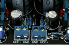
A pic of the voltage regulator board I recommend is attached below. You can see there are two sets of output terminals. Each set has on terminal labeled VCC+ and the other terminal is labeled GND. The two sets of terminals are not connected to each other, instead there are two completely separate voltage regulator circuits on the board. Therefore, you can think of each set of terminals as though they are really + and - (i.e. the + and - ends of a voltage source)
(instead of VCC+ and GND as the board is labeled).
What I do is use color coded wires: Red is +, Green is for the dac ground, and Black is for -
So, for the regulator output on the right, I would connect the red wire to VCC+
A green wire would go to GND.
For the regulator output on the left, I would connect a green wire to VCC+ (so now there will be two green wires connected at the power supply).
The black wire would go to the terminal labeled as GND.
At the dac board, the red wire goes to +
Both green wires go to ground
The black wire goes to -
I back so maybe I can try to explain better. The DAC does NOT have an AC input. It can run on plus and minus DC power rails, with a ground. Or, it can run with plus DC and ground instead. The best option is to use plus and minus power rails (+-15v).
Whether you use the regulators and transformer I recommend is up to you.
If you don't do the output stage and AVCC mods then it probably doesn't matter as much what power supply you use because the sound won't be very good.
On the other hand, if you want to modify the dac to make it sound better, then it might be worth using the recommended power supply and transformer.
A pic of the voltage regulator board I recommend is attached below. You can see there are two sets of output terminals. Each set has on terminal labeled VCC+ and the other terminal is labeled GND. The two sets of terminals are not connected to each other, instead there are two completely separate voltage regulator circuits on the board. Therefore, you can think of each set of terminals as though they are really + and - (i.e. the + and - ends of a voltage source)
(instead of VCC+ and GND as the board is labeled).
What I do is use color coded wires: Red is +, Green is for the dac ground, and Black is for -
So, for the regulator output on the right, I would connect the red wire to VCC+
A green wire would go to GND.
For the regulator output on the left, I would connect a green wire to VCC+ (so now there will be two green wires connected at the power supply).
The black wire would go to the terminal labeled as GND.
At the dac board, the red wire goes to +
Both green wires go to ground
The black wire goes to -
Attachments
Last edited:
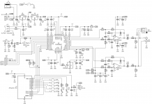
The other question was about using some additional regulators such as LT3042, that is only for if you want to remove the 5v and 3.3v regulators from the dac board and use your own 3.3v regulators instead. The existing 5v regulator uses the +15v for input and drops it down to +5v, then another smaller regulator drops the +5v down to +3.3v. That +3.3v is used to power the dac chip, the clock, the MCU, the optical receiver, and the SPDIF buffer inverter (everything that needs +3.3v power).
If the +5v and the +3.3 regulators are removed from the board, then we could talk about how to replace them with better regulators. In that case the +15v and -15v power would only be used for the opamps. However, best to keep it simple if you are having trouble understanding.
The +5v and +3.3v regulators I am talking about are labeled U1 and U2 on the schematic attached below.
Attachments
Last edited:
Mark,
Can you please point to where a more readably version of the schematic in your post 7159 can be found, or maybe post a pdf of it?
Can you please point to where a more readably version of the schematic in your post 7159 can be found, or maybe post a pdf of it?
- Home
- Source & Line
- Digital Line Level
- ES9038Q2M Board