It is possible that I will not even increase the input frequency. I will enter through USB Amanero.
The best sound is with ultra low jitter DSD, IMHO. Upsampling is one way to reduce jitter, which is why I like to do it in hardware just before the dac chip. Conversion to DSD avoids the sound of the PCM interpolation filters which are not good enough IMHO if the dac is otherwise very well implemented. With all the mods the dac is pretty well implemented and the AK4137 approach sounds best of all the options I have tested. A low cost AK4137 board is only about $30, so I don't think price should be a limiting factor. Also, with upsampling to DSD in hardware, its fine to use any XMOS, Amanero, Amanero clone, etc. They all sound the same here, which is to say they are all really good sounding.
I analyzed the reverse sides of the boards. and figured out the schematics
Me too.
")
I get it .. a little jitter is very good !!! Thank! Especially since I have familiar Chinese people and they can bring me with taobao directly, not through mail. It is cheap very). I will take a clone amanero. How difficult is it to realize an input frequency boost through the AK?The best sound is with ultra low jitter DSD, IMHO. Upsampling is one way to reduce jitter, which is why I like to do it in hardware just before the dac chip. Conversion to DSD avoids the sound of the PCM interpolation filters which are not good enough IMHO if the dac is otherwise very well implemented. With all the mods the dac is pretty well implemented and the AK4137 approach sounds best of all the options I have tested. A low cost AK4137 board is only about $30, so I don't think price should be a limiting factor. Also, with upsampling to DSD in hardware, its fine to use any XMOS, Amanero, Amanero clone, etc. They all sound the same here, which is to say they are all really good sounding.
I'm friends with a soldering iron. but raising a foot on a small chip is quite laborious.
It is also possible to avoid lifting a foot and instead cut some small traces, then solder small 30 gauge wire wrap wire on them. I have done that too and posted pictures and instructions for doing it either way. Besides, even if pin lifting fails and the MCU is ruined, it doesn't matter. We can control the dac chip with the Arduino anyway, keeping the MCU is just for convenience.
And?)) everything is so bad?))Me too.
How difficult is it to realize an input frequency boost through the AK?
It is no problem at all. It is designed to do that and the firmware makes it easy. You just push some buttons to configure it.
MCU is it logic? is it not a chip of es9038q2m?
No, the MCU is a separate microprocessor on the dac board (or the AK4137 board). They all have one. That's where the firmware is to make the dac work.
It's good)It is no problem at all. It is designed to do that and the firmware makes it easy. You just push some buttons to configure it.
Hi Kay,
5532 is not recommended for AVCC. Probably better to save it for another project.
Mark, have you tried 5532/5534 for the AVCC buffer? I know it is not the ESS top choice. I have been using these opamps for similar applications. the point here is the stability because of some batches of 5534 generate unless compensated. and the ringing of course upon those load transients... but who has measured this in the real board ???
eziitis,
So far as I know only ESS has measured dac performance with 5532 and found increased distortion using them.
One of the problems we have in this project is that it is being conducted with minimal test equipment. It is enough, in my view, if we can complete a good working dac design at all first, before worrying about optimizing in ways such as price/performance. Of course, I have no objection if somebody else who has the equipment wants to start going through measuring performance variations with cheaper parts. However, I can think of other places I would like to start with first besides opamps. The whole AVCC solution we use works well, but there may be other topologies that work just as well and are easier and less costly to implement. I would also like to better understand about my experiments with film caps in power supplies vs what I find with electrolytics and ceramics. I know there are other effective solutions out there, but I don't know the specifics of what can work just as well as film (especially if using SMPS). Moreover, right now I don't want to stop other development efforts to start work on those fine tuning types of things. We have working high sound quality solutions even if they may not be price/performance optimal. They are not too expensive to use for now, is the critical thing. Its more important at this point to keep making progress seeing what can be done better with AK4137, and perhaps seeing what can be done to improve interpolation filtering for PCM audio, including effective management of intersample overs. Those are some much bigger questions that need attention rather than, "can we use a 50-cent opamp for AVCC?"
Last edited:
eziitis,
.... Those are some much bigger questions that need attention rather than, "can we use a 50-cent opamp for AVCC?"
right, but sorry for being so nasty. there are not any measurements from ESS either. their top one is AD797. so what in fact is wrong with 5532/5534 in AVCC? nothing in fact, if we show some sort of creativity and go EE way not PA...
ok, I very much disagree with a modding approach where no single measurement was appropriately done and published, but I pay every respect to you running this project and all the effort to help other enthusiasts to go ahead.
Happy New Year and I wish you to find the sound!
Attachments
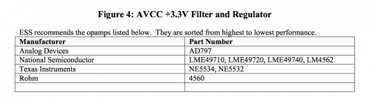
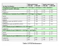
What ESS did publish with some numbers on it was the chart attached below. Taking that into consideration along with the fact that Benchmark used LME49860 opamps for DAC-3 (although I don't think they could have used it for AVCC since they are using ES9028PRO), I decided that I wouldn't go any lower than LME49720, and I haven't.
Also, back then ESS did not test OPA1612, but they use it now for ES9038PRO evaluation board. I think it sounds best now that I have the dac working this well and especially film caps on the +-15v rails. I was trying to reduce sensitivity to different opamps when I tried that. It helped a lot, but caused problems using AD797 for AVCC.
Right now, I will only recommend what I can say I know works. If I don't know that something won't work, I still might not recommend a beginner to try playing around with it. If more experienced guys want to do their own troubleshooting and analysis, they are welcome to. Please don't try to talk the new guys into it though, they have enough in front of them as it is. Besides, if they stick with what I can say I recommend, I think they should get good results.
EDIT: Regarding measurements, Richard Marsh helped with taking a set of measurements on the first dac, but it was an imposition on him as it was. I don't want to impose again. Also, I have looked at some FFTs in Arta when adjusting HD compensation. I don't have a super low distortion A/D, but I have a notch filter that makes it workable. While I can't say I can prove the calibration is accurate, I personally feel confident all the 1kHz harmonics are down around at -120dB or lower, most closer to -130dB. None look any worse than -120dB. What they add up to for THD, I don't know. Don't really care either. I did see a little bit of power frequency harmonics, so I added more filter caps and adjusted the regulators, but haven't checked again. My main concern is to know it isn't broken and that it is working about as well as good Q2M implementation should. Measurement-wise, I have no concerns of problems there. However, static measurements of HD @1kHz are of little worth for dacs, just so long as they aren't awful. There is much more to proper measurement of a dac, and someday maybe we can do a full set. Right now I am happy to keep working on sound quality goals and comparing with DAC-3. It works for me, to my satisfaction, if perhaps not to yours.
Attachments
Last edited:
eslei,
Don't think a block diagram should be necessary. Right now it is simply: USB2 -> Amanero(or XMOS) -> I2S -> AK4137 -> I2S -> ES9038Q2M. Audio signal flow and clocking both follow the same order, from left to right.
What I am starting work on is to see if I can keep audio signal flow the same, but make ES9038Q2M the master I2S clock source for AK4137 output timing, especially for DSD output mode.
Does that help?
Right now it is simply: USB2 -> Amanero(or XMOS) -> I2S -> AK4137 -> I2S -> ES9038Q2M. Audio signal flow and clocking both follow the same order, from left to right.
the device and os before USB2?
thanks
- Home
- Source & Line
- Digital Line Level
- ES9038Q2M Board