Can you say something about this version?
Nobody here that I know of has ever modded a version like that one. They seem to have appeared on the market only fairly recently. Without looking at one carefully, top and bottom, I couldn't say how easy or difficult it might be to mod. However, from the pictures it looks like it is probably not one I would recommend to buy for modding.
I will not use this - bad sound. Now I use Asus xonar d1.
They all sound bad until we mod them. That includes the green ones and the blue ones. It takes a lot of work to make one sound better than Asus Xonar, but they can sound much better if you do all the work.
what abut this?
No. That one is junk. I bought one to see if it would be better for modding, but its not worth bothering with. Please avoid that one.
first, 🙂 many many thx to "markW4" for his really really profound knowledge of modding and sound-quality improving !! i´m absolutely surprised about his knowledge again and again !! second, i have an Asus Xonar DX here and it was the main reason to "swap-over" to the ES-boards.. absolutely no comparison to some green or blue ES9038Q2M (or ES9028Q2M)..the ES-chips/board are absolutely far superior to these Asus-cards !! (but i would also recommend only to use our "old" green "standard" SMP CP-boards (up to 1.07) or some blue Y´s (they are only (the blue ones) a little bit worser; by 5-10% i guess (have the two versions here)).. by that i had an Cambridge Audio-DAC-Magic here (150€) and there it was absolutely the same: there were Wolfson-chips in it (the "high-end" Burr-Browns) and it was also absolutely no comparison to what ES-chips are capable of (soundstage,3D,resolution) !! so conclusion: only buy our "standard/old" green smp cp or blue Y´s..🙂
Hello Markw4 & others,
I've been watching this thread for sometime now. I’m a beginner in modding so took me many hours of reading the big thread to begin to understand some.
I have the blue board with 12v supply. I’d like to try some of the mods that Mark made, with smd using surfboards (9801, 9161 etc) as he mentioned. I’ve begin process of identifying and adding some of the parts in Mouser and Digikey building up my Shopping Cart.
I’d like to attempt the clock, dvdd, avcc and output stage for a start based on the BOM v3.
I have several questions as you can imagine.
1. For the 22uf Wima or 47uf alu poly cap in AVCC(C8,9), What is the preference? Or is there smaller smd part perhaps to use?
2. Do you think it would be possible to fit the whole avcc in a surfboard 9161 – 16pin, with the ltc665 and opa1612 side by side?
3. Is it advisable to use OPA1612 for both avcc and output stage?
4. What kind of smd parts should I look for, eg. x7r caps, .1 thin film resistors?
5. Any other suggested changes from the BOM v3?
Thanks in advance.
Regards,
Kay.
... : only buy our "standard/old" green smp cp or blue Y´s..🙂
well, first off, to me the components on the board look a way better than on the blue one. secondly, it has 2x3,3V regs and the layout looks ok for a Chinese garage design, what also the original board is. done by "Skysong", and judging from your blog you have been using some stuff from this brand as well.
how may it sound? nobody knows, but AVCC caps look a little more serious than on the original. so it may have less 3rd harmonic then.
modding... since the "full mod" basically messes up everything that on the source board is, then as long as it contains an es90038q2m chip this should be fine.
1. For the 22uf Wima or 47uf alu poly cap in AVCC(C8,9), What is the preference? Or is there smaller smd part perhaps to use?
Hi Kay,
I will try to see if I can address your questions adequately.
Regarding the big 22uf Wima caps I tried for AVCC, they are pretty huge and if I had it to do over I might try something small and also try to get them a little bit more out of the way, although not too far away. Regarding capacitance, in the application note at the ESS website downloads page, they suggest 10uf to 47uf for AVCC caps. The range was to assure freedom from oscillation with some opamps. I suspect the opamps I have been using would probably work with the minimum of 10uf. ESS also used electrolytics, and I don't know if it matters or not. However, I noticed that Mouser had some Panasonic SMD stacked film caps in stock up to 10uf (at probably low voltage) which I think probably ought work for AVCC opamp output caps and also for LTC6655 output filter caps. If I had not been requested to use through hole components I might have given those a try. But, then if I had not been requested to use through hole components I probably wouldn't have modded another dac board. At this point I believe it was a good thing that I did, so it turned out okay.
2. Do you think it would be possible to fit the whole avcc in a surfboard 9161 – 16pin, with the ltc665 and opa1612 side by side?
They might be able to fit close together, but so far as I am aware they are not available in the same size packages, so they would each need different adapter boards, or different surfboards.
3. Is it advisable to use OPA1612 for both avcc and output stage?
OPA1612 are my opamp of choice for the output stage at this point, which is something I decided sounded better after I added film caps to the +-15v rails. Haven't tried it for AVCC yet, although I have been meaning to. Should be fairly easy since I have a socket on the AVCC board, but I have to remove the dac board from the test setup to get at the AVCC opamp to swap it out. Therefore, don't know when I will get around to trying it. Don't know why it wouldn't work though, I think it should.
4. What kind of smd parts should I look for, eg. x7r caps, .1 thin film resistors?
We would use the same kind of components if modding with leaded parts. Opamp power pin filter caps are X7R and Tantalum (I started using tantalum polymer for low ESR, but they are larger size). For output stage filter caps in the signal path use C0G or NPO. Use the best thin film resistors you can find in tight tolerances (.05% or .01% if possible, in order to best help cancel out common mode distortion and noise). Susumu and Vishay are good resistor brands to look for. You can look at their datasheets on Susumu and Vishay websites to see which series thin film resistors are the most linear (low distortion). You might not be able to find the best ones in the values you need, but use the best you can find would be what I would probably do myself.
5. Any other suggested changes from the BOM v3?
Sometimes you may find it helps to use rather fat gauge wire for opamp power pins. So long as its not too thick to manage okay, you might find it helps with sound quality. For most other purposes I use a lot of 28 or 30 gauge wire wrap wire for interconnections of signals. Wire wrap wire from Mouser costs more than from Amazon, but the insulation is much more rugged and tends to shrink less from soldering heat. It is harder to strip though, so some good strippers are useful.
In addition, you may have noticed I started using gold flashed or gold plated pin headers for I2S connections on the dac board and the AK4137 board. I also have added extra ground pins so I can use ribbon cables for I2S connections with every other wire being a ground to help provide a little shielding. It does help. Or, you probably could use u.fl connectors, if you want. I would just keep the wires close together in that case so you don't create ground loops.
If you look at what I have done most recently after the output stage and AVCC schematics were posted, was I added some more voltage regulators around the clock and dac chip, and also used better X7R and tantalum polymer filter caps to replace the stock filter caps in that area. The tantalum polymer caps I had in stock were bigger and too wide to go on the existing solder pads without some solution, so I put them on their sides.
Guess that's about all I can think of at the moment. If more questions come up or if I didn't answer adequately, please let me know and I will try help out. Good luck with your project. Please keep us informed and post some pictures from time to time. Maybe someone else will want to mod a dac similar to what you do, so some info, tips, photos, etc., can be helpful for the people that come along later. Thanks in advance for anything you can do in that regard. 🙂
Hi Mark,
Thank you very much for the explanations. Invaluable.
I will inform and post when I do the mods.
Am afraid it will take awhile to get the components. Plus me being a starter without any experience I hope I can actually make it work.
When I start the work, I bet I'll have much more questions than you guys can handle.
Cheers.
Hi kaytata,
When you say you are a 'starter,' I am not sure exactly what you mean by that. If you mean you have not worked with SMD parts before, then I would strongly recommend to get an SMD soldering practice kit from ebay or Amazon and watch some youtube videos on how to do it.
In addition, be sure to look carefully at SMD part sizes before ordering. Surfboards only work with a certain range of SMD part sizes, and some SMD parts can be way too small for practical hand soldering.
You might also want to get a syringe of paste flux which can be useful if you need to unsolder pin headers or other things where some extra flux can help. The paste flux can tolerate more heat for longer times than liquid flux can. When removing pin headers, I pry off or cut away any plastic parts leaving only the pins. That way they can more easily be unsoldered and removed one at a time. If any solder left in holes, I use a stainless steel sewing needle a little smaller than the hole. The needle is held in pin vise and heated along with the board at the hole. When the solder starts to soften I push the needle through the hole and remove heat. Wiggling around the needle lets it come out leaving an open hole. Solder doesn't stick to stainless steel very easily is why that works. However, I have seen paste flux allow solder to stick to it. In that case I have had to cut off the needle near the hole to get out. I use a Dremel tool and cut off wheel for that, and for various other things too. Dremel tools can be very handy, IME.
For unsoldering multiple pin devices such as the clock, it really helps to have some Chip Quik available. It works like magic in those cases.
-Mark
Hi Mark,
By starter I mean, I do not have that much experience. Have done some odd soldering of connectors etc. I did manage to desolder the tiny avcc smd resistor looking at the modding pdf done by another member, Sergelises I think. Then I powered the avcc with a 5v lt3042 board filtered by a tps7a4701evm set to 3.3v(albeit both left and right together). I could hear an improvement in the sound.This got me thinking, I got to try the mod.
Yes, I've been watching a lot of youtube lately. I'll use the techniques that you mentioned, and on other posts too. Very thankful for that. And I do have dremel. I do carpentry as a hobby.
Regarding SMD sizes, thanks for pointing that out. Am I reading it right that the 9801 surfboard accepts 1206 and 0805? And you mentioned that ltc6655 and opa1612 are not the same size, that must mean soic8 and msop8 are different sizes?
I also wanted to try lt1763s you mentioned in other posts. Will the 9801 board fit them?
Would +/-12v work for powering the op amps?
Sorry, so many questions.
Thanks for your help.
Kay
Hi kaytata, If any solder left in holes, I use a stainless steel sewing needle a little smaller than the hole. The needle is held in pin vise and heated along with the board at the hole. When the solder starts to soften I push the needle through the hole and remove heat. Wiggling around the needle lets it come out leaving an open hole. Solder doesn't stick to stainless steel very easily is why that works.
-Mark
8 pcs/Set Non-Sticking De-soldering Hollow Needle Tool Pin for IC Extraction | eBay
Hi Mark and seasons greetings 🙂
Today I tried my first smd de-solder and re-solder and it went surprisingly well !
I needed to re-assign an i2c address on an oled and it had an smd resistor and two position options...
Enough heat before starting and a good pair of tweezers...
Oh, and it helps being a jeweller ... I know what 'flow' looks like and how to set-up for best control.....
At these daily navigation's electronics seems pedestrian..
Soldering: Gold & Silver Solder Melting Points & More - Interweave
Try that with a gas torch...😉
Last edited:
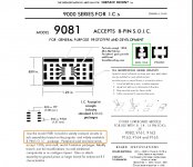
Am I reading it right that the 9801 surfboard accepts 1206 and 0805?
Hi Kay,
Those are the sizes of SMD parts (in .1 inch units and decimal point omitted, IIRC) that are the maximum and minimum it can accept given the pad sizes and the spacing between pads. If you look at the surfboard data sheet there is a diagram showing how they might fit. Please see attachments below.
And you mentioned that ltc6655 and opa1612 are not the same size, that must mean soic8 and msop8 are different sizes?
The cases are a little different, but not necessarily enough not to fit on surfboard pads. If you google those part numbers and download the data sheets, there are size diagrams showing the dimensions (which you can use to check and see how they will fit).
Some resources that might be of use now or later:
Lots of Data on SMD IC cases:
http://www.topline.tv/SMT_Nomenclature.pdf
Data Sheet (pages 19 & 20, in this instance):
https://www.analog.com/media/en/technical-documentation/data-sheets/1763fh.pdf
Package Drawings:
Packaging, Quality, Symbols & Footprints | Design Center | Analog Devices
Wikipedia:
List of integrated circuit packaging types - Wikipedia
Huge Array of SMD Adapters Available (e.g.):
Proto Advantage -
Attachments
Mark, Thanks a lot for the set of resources. Will study and decide what to order.
Cheers & Happy holidays!
Kay
Cheers & Happy holidays!
Kay
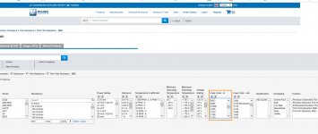
Test setup is configured to start working on AK4137 I2C programming. Captured its boot up sequence to the AK4137 I2C registers using the little cheapie logic analyzer in the pic below. Text file with decoded I2C is attached also if anyone cares to take a look and compare it with the AK4137 data sheet to see what its doing.
In the I2C capture file, the address of the AK chip is 0x20 which is seen associated with each bus transaction. The first write of each pair of writes is the register address to be accessed, with registers 0-5 being used here (a register 6 exists too). The second write in each pair is the register data to configure the chip.
In the I2C capture file, the address of the AK chip is 0x20 which is seen associated with each bus transaction. The first write of each pair of writes is the register address to be accessed, with registers 0-5 being used here (a register 6 exists too). The second write in each pair is the register data to configure the chip.
Attachments
Last edited:
want to continue. I do not recommend using blue cards. I had experience using products from this company. On the boards they soldered poor-quality elements. Plus there are reviews on the Internet about the DACs of this company. They sound worse. This is my experience and wanted to share it. Go to taobao and find this company "YJ". There you will find their products.
Also about the green card from Sky Song. Mark, You have had experience using products from this company. Can you say the quality of performance? The fact is that as indicated eziitis in this board there are two stabilizers. One goes to logical control. The other is powered by the digital part. And so I think that the board wins before being discussed here. By construction, the rest is the same. I studied yesterday fees for photographs from stores. As for the capacitors Nichicon and Elna, they are most likely fake. Judging by the size. I had the experience to see such. Often in frequency they are not of high quality. Also ESR too bad. Therefore, I would recommend to check them on the boards, if someone plans to leave them on the boards.
Mark, Have you had experience using products from? As indicated eziitis, the board has two voltage regulators. One goes to power logic control. The other is powered by the digital part. Here the fee wins. And by filtering the voltage also wins before being discussed. Otherwise, they are the same (not counting the logic). If the quality of y, on the level, I would buy this version.
Mark, And so you're good! Work done serious. I have not mastered the whole forum ...) but I understood the main points for improvement:
1. Improving nutrition AVCC
2. to exit I V
3. Increase the input frequency through AK
4. Replace the crystal clock.
I think that will stop there. It is possible that I will not even increase the input frequency. I will enter through USB Amanero.
1. Improving nutrition AVCC
2. to exit I V
3. Increase the input frequency through AK
4. Replace the crystal clock.
I think that will stop there. It is possible that I will not even increase the input frequency. I will enter through USB Amanero.
888777,
I appreciate your concerns. However, as ezitis correctly said, if you decide to fully modify the board you buy, about the only thing that will still be used is the dac chip, the ground plane, and maybe some of the connectors. I do still use the stock 3.3v regulator for the MCU only. Everything else goes.
Now, if you are not sure if you want to do all the mods, or if you know you don't intend to, then that would be very different and I could understand your concerns. As I said in one post before, the main reason some people get a green SMPCB (sp?) board with the display is so they don't have pin lift any of the pins on the MCU to get control of the I2C bus. Probably better just to learn how to deal with some small work though, since I don't have a way to avoid pin lifting on an AK4137 board, which may be one of the next mods if I can get it working satisfactorily.
there is a forum hi-fidelity-forum. There, a person from Ukraine has also done a lot of work on improvement. Here are such people as an example to everyone) Purposeful and disinterested! help the community. and for free. I studied improvement PCM5102 on that forum. As a result, I quit, because I bought a dac from YJ. Sorry of offtopic
I'm friends with a soldering iron. but raising a foot on a small chip is quite laborious. But it is possible) I am only worried that the elements on the board from sky song will be of poor quality. I do not want to repeat my sad experience ... As I definitely implement the power in the first place! I will do the output later ...
- Home
- Source & Line
- Digital Line Level
- ES9038Q2M Board