thank you Mark.
You are most welcome!
Say, while we are talking, may I ask if you had a chance to look at the instructions and pictures I posted a link to?
Dropbox - OSB.zip
Hi Guys,
May I ask if anyone looked at the prototype instructions I posted a link to? If so, you may notice the picture quality is poor. That happens when trying to embed a hi-res image into a text type of format as .rtf is. Therefore, I have concerns about using pdf files of instructions. Maybe it would be better to have a list of instructions with the names of the picture files to refer to? That way you could use the hi-res pictures to better see how the build should be. What do you think?
Yes I did.
thank you about that.
I can try it, but maybe you can do more step by step tutorial, with for each step put instructions, schematics and pictures.
What serge did, really helped me to understand what we are doing.
I am attaching pictures of what I am talking.
But I know that it is more work for you to teach dumbs like me
")
Attachments
Yes I did.
thank you about that.
I can try it, but maybe you can do more step by step tutorial, with for each step put instructions, schematics and pictures.
What serge did, really helped me to understand what we are doing.
I am attaching pictures of what I am talking.
But I know that it is more work for you to teach dumbs like me
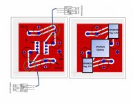
I already provide the schematic. I provided a layout diagram for the output stage. I made a list of instructions, and where there are bigger spaces between some of the instructions, I have pictures to go in there to show what I mean by the instructions. Okay?
The problem is my pictures are hi-res, and some of Serge's pictures and schematics are very low-res. I can't put my pictures on the same paper as the instructions and schematic. Or, let's put it this way, I don't know if I could, but right now I can't. So, can you live with a schematic on one paper, instructions on another paper, and pictures on separate papers or look at them on the computer? I am not making these things with plans to sell thousands of kits. I need to make it good enough beginners can get by and feel they can do it, but I don't need better than that. So, given my constraints above, is what I am able to offer going to be good enough, or are there small changes I can make to help?
Maybe you can just put lowres pictures in the pdf and provide referenced highres pictures in a downloadable zip.
Just my 2 cents
Ok.I already provide the schematic. I provided a layout diagram for the output stage. I made a list of instructions, and where there are bigger spaces between some of the instructions, I have pictures to go in there to show what I mean by the instructions. Okay?
I knew you provided all that in different posts in the thread.
But sometimes, I was lost and didn’t understood if it was differents steps of the mod or different tries you made of different layouts and differents composants.
Not your fault. Lack of knowledge.
I think I need a doc going frome step 1 to step n with a clear bom.
But I only speak for myself and my needs.
Hoping to get the AVCC board finished up over the weekend. My next task after that can be to work on assembly instructions and work with bih on the BOM.
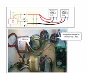
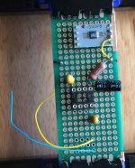
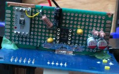
For today, I have a few more pics showing continued progress on the AVCC board. I did find that I needed to notch out a little clearance in one corner of the AVCC board where it might contact the TOSLINK connector pins on the dac board. Also clipped off some excess length of TOSLINK connector pins.
The loose ends of the yellow and blue wires will go to the Vref dividers, right around those holes in the board where the wires are sticking out.
Attachments
Last edited:
Ok.
I knew you provided all that in different posts in the thread.
But sometimes, I was lost and didn’t understood if it was different steps of the mod or different tries you made of different layouts and different components.
Not your fault. Lack of knowledge.
I think I need a doc going from step 1 to step n with a clear bom.
But I only speak for myself and my needs.
+1 here.
@Mark @Drone,
thank you for all the info.
For now, I connect to the board via I2S only : rpi3->kali reclocker->dac Board
Do you think connection via usb and xmos like Drone will be better?
If yes, Do you think this xmos is ok?
XMOS +CPLD U208 DAC daughter card USB digital interface I2S DSD output Suitable AK4497 ES9018 ES9028 ES9038 DAC decoder board-in Amplifier from Consumer Electronics on Aliexpress.com | Alibaba Group
or do you have better models to advise(in a reasonable price range)?
If you are not playing DSD files but simply using the AK4137 to upsample PCM to DSD then you shouldn't need a USB board at all.
Simply connect the I2S output from the Kali or Pi.
In fact there is a Pi Hat version of the AK4137 that I think does DSD file input too... (although it does not have the LCD display that the stand alone board has)
Raspi-4137 Raspberry Pi Digital Network Player Supports 32bit 384K DSD256 | eBay
I use both the basic XU8 usb to I2S (which is the previous series to the one you linked) and a DIYinHK XMOS XCORE-200 XU216 which is the series after your linked XU208
XMOS 384kHz DXD DSD256 high-quality USB to I2S/DSD/SPDIF PCB - DIYINHK
I have several different devices and O/S' and some, such as X86 PC's ,don't have I2S out. Thus the need for a usb interface.
I recall that Mark uses Windows PC so needs Usb to I2S too.
Last edited:
Suppose I make zip files containing instructions (including lo-res pics), BOM, schematic, hi-res pics, and layout diagram (if available) for the through hole component mods. The file size is going to much, much larger than what I can attach to a diyaudio post. (I can't even post one really hi-res pic.) Where would be a good place to host it so people can get it?
Suppose I make zip files containing instructions (including lo-res pics), BOM, schematic, hi-res pics, and layout diagram (if available) for the through hole component mods. The file size is going to much, much larger than what I can attach to a diyaudio post. (I can't even post one really hi-res pic.) Where would be a good place to host it so people can get it?
Hi Mark,
Dropbox works, or you could post the Hi-res to a photo hosting site like 'Flickr' or '500pix' or similar with free hosting then link here...and attach here the bom, layout, and schematic ...should fit fine..
cheers...bob
If you are not playing DSD files but simply using the AK4137 to upsample PCM to DSD then you shouldn't need a USB board at all.
Simply connect the I2S output from the Kali or Pi.
In fact there is a Pi Hat version of the AK4137 that I think does DSD file input too... (although it does not have the LCD display that the stand alone board has)
Raspi-4137 Raspberry Pi Digital Network Player Supports 32bit 384K DSD256 | eBay
I use both the basic XU8 usb to I2S (which is the previous series to the one you linked) and a DIYinHK XMOS XCORE-200 XU216 which is the series after your linked XU208
XMOS 384kHz DXD DSD256 high-quality USB to I2S/DSD/SPDIF PCB - DIYINHK
I have several different devices and O/S' and some, such as X86 PC's ,don't have I2S out. Thus the need for a usb interface.
I recall that Mark uses Windows PC so needs Usb to I2S too.
Thank you Drone,
Very clear.
As I have many DSD 64/128/256 files(for now played with DOP) I will go for xmos.
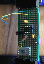
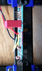
Again, more pictures of the AVCC board coming together. Some of it is getting harder to see especially around the opamp socket where there are more wires now. I soldered on some leads to go the 47uf AVCC caps on the dac board and slipped wt/gn/yel sleeving over them for now. Big red and black wires are for +-15v. Decided to go ahead and use the 10k MF resistors I have in stock even though they are kind of big. It was either that or SMD and I decided to stick with the program. Thus, Vref dividers/filters are soldered in place. The opamp input filter is soldered in place. Getting pretty close to the end of the AVCC board.
Pictures below.
For tomorrow: No pictures of it yet, but right now working on attaching the AVCC board to the dac board. That may be hardest part of this whole thing, but it was all I could think of to use through hole components and put the AVCC board close to where AVCC voltages are needed. More on that later.
Attachments
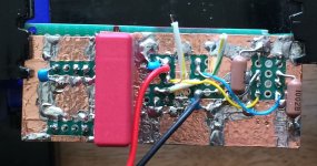
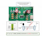
Whew! No kidding, that last bit of AVCC board work was a bit nerve-racking, but it's done.
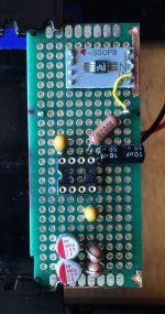
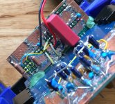
Pictures below. Green blobs at the outside corners of the AVCC board are classic green epoxy putty. AVCC board ground plane is soldered to dac board on both sides of AVCC board. I used SMD 47uf caps on the dac board, took off the plastic spacer on the bottom, and stuck the short, flat leads through the holes in dac board. One can see that where the ground lead is soldered to the dac board it is flat. Would have been fine if it was round too.
In one of the AVCC board pics, Vref attachment points are outlined in yellow, and the where +5v will connect to LTC6655 is outlined in red.
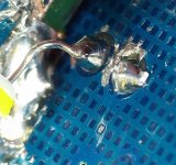
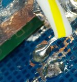
Some closeups are included of where AVCC power wires are soldered to the 47uf cap pins on the bottom of the dac board. Probably would have been easier if I had used caps with longer leads which could have been sticking out more for easy access, but it worked out okay. The AVCC power wires were stripped of insulation, and a bit of sleeving slipped over them to help keep them from shorting to anything they shouldn't. Thought that might be easier that trying to strip short pieces of small wire which can bring its own problems.
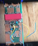
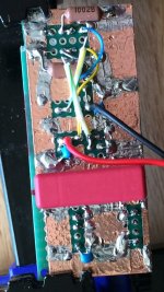
I'm sure there are other ways to do this and many variations that would be similar. The big film cap was hard to figure out what to do with and I'm not sure if I were to do this again if I would arrange the components exactly the way I did. I don't know if there is a best way in this case. It was thinking about ending up with something like this that convinced me I would prefer doing SMD AVCC power for the first board, which of course is what I did.
I also still think the AVCC board could have been done pretty much just as well from the side as I had originally planned. Only building both ways, from the side, and here in the middle, and comparing results would convince me one way might be better than the other.
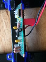
On the other hand, the output stage for this version seems fine from a location perspective. It would be an easy place to do SMD or through hole. No real compelling reason to do the first board output stage the way I did except to keep all the mods compact and on a single piece of PCB material.
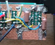
There is some more work to do to finish wiring up power and finding some place to put RCA analog output connectors since I already removed the original ones.
Also, at some point this board needs a clock upgrade and I2C bus connectivity mods. One thing at a time.
Pictures below. Green blobs at the outside corners of the AVCC board are classic green epoxy putty. AVCC board ground plane is soldered to dac board on both sides of AVCC board. I used SMD 47uf caps on the dac board, took off the plastic spacer on the bottom, and stuck the short, flat leads through the holes in dac board. One can see that where the ground lead is soldered to the dac board it is flat. Would have been fine if it was round too.
In one of the AVCC board pics, Vref attachment points are outlined in yellow, and the where +5v will connect to LTC6655 is outlined in red.
Some closeups are included of where AVCC power wires are soldered to the 47uf cap pins on the bottom of the dac board. Probably would have been easier if I had used caps with longer leads which could have been sticking out more for easy access, but it worked out okay. The AVCC power wires were stripped of insulation, and a bit of sleeving slipped over them to help keep them from shorting to anything they shouldn't. Thought that might be easier that trying to strip short pieces of small wire which can bring its own problems.
I'm sure there are other ways to do this and many variations that would be similar. The big film cap was hard to figure out what to do with and I'm not sure if I were to do this again if I would arrange the components exactly the way I did. I don't know if there is a best way in this case. It was thinking about ending up with something like this that convinced me I would prefer doing SMD AVCC power for the first board, which of course is what I did.
I also still think the AVCC board could have been done pretty much just as well from the side as I had originally planned. Only building both ways, from the side, and here in the middle, and comparing results would convince me one way might be better than the other.
On the other hand, the output stage for this version seems fine from a location perspective. It would be an easy place to do SMD or through hole. No real compelling reason to do the first board output stage the way I did except to keep all the mods compact and on a single piece of PCB material.
There is some more work to do to finish wiring up power and finding some place to put RCA analog output connectors since I already removed the original ones.
Also, at some point this board needs a clock upgrade and I2C bus connectivity mods. One thing at a time.
Attachments
Last edited:
An updated attempt and making an output stage instruction sheet is available here: Dropbox - Output Stage Instructions.zip
Persons interested in building the mod please take a look a let me know how close it is coming to making it possible for you to figure out how to make the output stage board.
So far as I am able to tell, it is not possible to make it a whole lot easier. At some point one will need to look at the schematic, layout drawing, and pictures to get an idea of how to proceed with soldering parts together. If the color coding in the last couple of images is helpful, I could possibly add it to the layout drawing as well, or you could. Whatever will help simplify the project from impossible to doable, if not necessarily simple.
Thx.
An updated attempt and making an output stage instruction sheet is available here: Dropbox - Output Stage Instructions.zip
Anyone?
Anyone?
Hi Mark.
I just look to your doc.
It looks ok for me to start.
I guess I will need help
) , but it's a go!thank you
Do you have a definitive BOM to provide?
Or the one provided by bih ok?
https://www.diyaudio.com/forums/att...537303575-es9038q2m-board-bom-outputstage-zip
Or the one provided by bih ok?
https://www.diyaudio.com/forums/att...537303575-es9038q2m-board-bom-outputstage-zip
The BOM bih made is good except for one part for the AVCC board. That part is the 47uf AVCC filter cap that goes in the dac board. He has it has being tantalum, but it should actually be aluminum electrolytic or aluminum organic polymer.
and how does it sound? perhaps some measurements also would help.
checked your LPF values on ES9028pro board. how did you calculate them?
with an AD797 I am getting -98db, but only with AD797...
How does what sound?
What ES9028PRO board?
- Home
- Source & Line
- Digital Line Level
- ES9038Q2M Board