Hi Andy,
Welcome to the group in a more active capacity. You could do SMD, for sure. Although we are trying some new output stage and AVCC schematic variations, my first implementation use very compact SMD. No problem if you prefer to build with SMD and you have the skills to work out the details. Perfboard and copper tape should be okay.
Regarding analog and digital grounds, they have to be tied together at some point, specifically at the dac chip. Other than that you are free to used separate supplies and grounds as you prefer. I would just emphasize that power supply coupled noise can be a problem with some 5v and 3.3v circuitry so care needs to be taken there in addition to ground. For +-15v circuitry, we are mostly talking about the output stage and AVCC supply opamps (if using opamps for either). Critical low voltage circuits include the clock, VCCA, and LTC6655 input power.
For an AVCC dual opamp, supply impedance to the opamp power pins should be very low or bass response may suffer, however you wish to make sure it is low enough would be fine.
Also, power supply ripple should be very low for the +-15 rails. Again, your choice as to how to make that happen.
Last edited:
Mark, I commend your dedication to the cause, sir! I'm just looking at a Pioneer PDS904 CD player that I have here. It's fully working but in truth, I just don't use CD's anymore. Do you think there would be anything inside worth salvaging for my DAC?
Hi Alex,
Probably nothing in the CD player to reuse. You could however still use it to play the occasional CD using the SPDIF or TOSLINK outputs so as to perform the D/A conversion with your new dac when it is finished. It might be useful as a test source in that regard.
Probably nothing in the CD player to reuse. You could however still use it to play the occasional CD using the SPDIF or TOSLINK outputs so as to perform the D/A conversion with your new dac when it is finished. It might be useful as a test source in that regard.
Ah yes. Good point. I'm presuming from reading through some of the earlier links, that my first port of call should be to purchase a ES9038Q2M as cheap as possible?
Don't know about as cheap as possible, the green boards are probably a little better made than the blue ones. Also, if you care to have it some of the boards are available with a display and optical remote control. Costs more, of course.
Also, as time goes by we see more variations of ES9038Q2M boards on the market. We have the most experience with the original green ones you see in most of the pictures in the thread. The cheapest one like that might be a good choice.
Prices might be lower at Aliexpress than at ebay. Not sure if there are other places to look for better deals. Price will also vary with delivery time, epacket may be a little faster than the cheapest, DHL is the fastest but costly. It can take quite some time for packages to arrive from China.
Last edited:
Hi Mark, thanks for your response.
Hi Andy,
One more though occurred to me about using some SMD parts.
If wanting to build using perfboard, soldering SMD parts directly to the board could spread out to cover a lot of area and also interrupt the ground plane more than might be desirable.
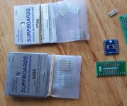
Besides using SMD to DIP adapters, there are some other adapters that could be used to help with some aspects of construction. I am thinking of SurfBoards as shown in the pic below. There are a few different versions, and they can be cut and trimmed down to fit as needed. The pins can also be removed and they can be mounted in any way that is convenient.
This was something I considered trying for some of the through hole component board circuitry because I would I have liked to use them in places. In the end I decided against it and stuck with leaded components since I think that was what people really wanted to see for that project.
Attachments
Something else I have been thinking about mentioning is not new, but it might be new to some people. It has to do with modern computer operating systems and intersample-overs.
It turns out Windows, MacOS, and possibly Linux by now, have multi-client audio systems so that multiple programs can access the default sound device at once. The complication arises because a sound device such as a sound card or XMOS board and only operate at one sample rate at a time. Therefore users may set the sample rate and bit depth they wish the OS to use for all audio output at all times that is to be routed to the default sound device. To make it work the OS has to perform real time sample rate conversion to any sound streams from applications that are not set the the default sample rate and bit depth.
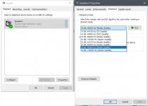
In Windows for example, there are sound card settings in the Windows control panel for each sound device. Please see the screen shot below. If a device is set as default, the sample rate Windows will use can be set as seen in the picture. The problem is that the sound quality of SRC is not very good, and with a good dac one can easily hear that the sound is not up to the quality it should be.
in addition, on the Level tab, the maximum level for the device can also be set. For modern dacs that use ASRC, and or if upsampling to DSD is being used, it should help lower distortion by reducing the output level by 3.5dB per resampling event that is anticipated. That might be overkill, as it is a very conservative estimation of what might be needed. One could listen to a loud highly compressed CD playing, turn down the level 3.5 dB or more and see if more than 3.5dB seems to help very subtle low level distortion at all. If you can't tell if more than 3.5dB is needed, it would probably be good to leave it set there. I find setting the level in Windows at 92 or 93 out of 100 seems to be needed so I don't notice any level related distortion.
Regarding what to do when playing music to avoid unwanted resampling by the OS, if there is only one sound device then it would be necessary to set the default sample rate and bit depth for whatever music is to be played. In theory, there are some checkboxes to allow sound card device drivers to grant control of the sound card settings to one app, but generally speaking nobody seems to be writing device drivers that can use that feature. So, it means manual selection is required.
Since the above is a very undesirable state of affairs for playing music of arbitrary sample rates, the best solution seems to be to have more than one sound device installed in the computer and set the one that you don't intend to use as default. The other thing is to install an ASIO sound driver for the sound device that you do want to use. If there is no specific ASIO driver available then the ASIO4All universal driver can be tried. The last part of allowing apps to set sound device sample rate and bit depth requires that the app itself can be configured to use the desired sound device with the ASIO driver.
For playing music on Windows, the music player app Foobar2000 can be configured to use ASIO sound cards although do so requires downloading a configuring an optional plugin. Once set up, Foobar will correctly set the sound card to play whatever music is in a playlist without any unintended resampling.
It turns out Windows, MacOS, and possibly Linux by now, have multi-client audio systems so that multiple programs can access the default sound device at once. The complication arises because a sound device such as a sound card or XMOS board and only operate at one sample rate at a time. Therefore users may set the sample rate and bit depth they wish the OS to use for all audio output at all times that is to be routed to the default sound device. To make it work the OS has to perform real time sample rate conversion to any sound streams from applications that are not set the the default sample rate and bit depth.
In Windows for example, there are sound card settings in the Windows control panel for each sound device. Please see the screen shot below. If a device is set as default, the sample rate Windows will use can be set as seen in the picture. The problem is that the sound quality of SRC is not very good, and with a good dac one can easily hear that the sound is not up to the quality it should be.
in addition, on the Level tab, the maximum level for the device can also be set. For modern dacs that use ASRC, and or if upsampling to DSD is being used, it should help lower distortion by reducing the output level by 3.5dB per resampling event that is anticipated. That might be overkill, as it is a very conservative estimation of what might be needed. One could listen to a loud highly compressed CD playing, turn down the level 3.5 dB or more and see if more than 3.5dB seems to help very subtle low level distortion at all. If you can't tell if more than 3.5dB is needed, it would probably be good to leave it set there. I find setting the level in Windows at 92 or 93 out of 100 seems to be needed so I don't notice any level related distortion.
Regarding what to do when playing music to avoid unwanted resampling by the OS, if there is only one sound device then it would be necessary to set the default sample rate and bit depth for whatever music is to be played. In theory, there are some checkboxes to allow sound card device drivers to grant control of the sound card settings to one app, but generally speaking nobody seems to be writing device drivers that can use that feature. So, it means manual selection is required.
Since the above is a very undesirable state of affairs for playing music of arbitrary sample rates, the best solution seems to be to have more than one sound device installed in the computer and set the one that you don't intend to use as default. The other thing is to install an ASIO sound driver for the sound device that you do want to use. If there is no specific ASIO driver available then the ASIO4All universal driver can be tried. The last part of allowing apps to set sound device sample rate and bit depth requires that the app itself can be configured to use the desired sound device with the ASIO driver.
For playing music on Windows, the music player app Foobar2000 can be configured to use ASIO sound cards although do so requires downloading a configuring an optional plugin. Once set up, Foobar will correctly set the sound card to play whatever music is in a playlist without any unintended resampling.
Attachments
Last edited:
Not much activity going on around here today, so I thought I might post a couple of pictures showing how the through hole project is coming along.
Since I removed the original output connectors, I decided to put some new ones down at the end of the output stage board. Another 10-15 wires and this part should be done enough to test.
Also decided the holes for the +-15 power input connections on the dac board are too small, so I moved where power comes in to the output board.
After testing the through hole board mods, that will leave a clock mod, I2C mod (occip type), and maybe some local voltage regulators for the clock and or VCCA (maybe one for them to share, not decided).
Also, pretty soon I need to get back to writing AVCC board instructions, although it seems pretty obvious without instructions from the pictures and the schematic (after doing the output stage board first), doesn't it?
Hope things are going well for everyone else.
Attachments

Last edited:
Hey Guys,
Question for you if I may. Those building through hole component board mods, after looking at the output stage board and seeing how it is constructed, do you think it is still necessary to have the same type of instructions to lay down the copper foil and solder parts in place, given the pictures and schematics attached below?
If building the AVCC board after the output stage board, it should be easy to do AVCC with less instructions, it seems to me, but maybe not to other folks. I don't know.
However, if one were contemplating building the AVCC board first, I guess without the experience of doing the output stage first, then more advice might be needed for AVCC? What do you think?
If it is needed for me to do it then I will do it, but being a bit lazy I wouldn't do it unless people still feel it is needed.
Attachments

It works! Sounds pretty good too, even before the clock and occip I2C mod. It needed the upsampled DSD though, which makes a big difference. First I tried 16/44 SPDIF and too much distortion.
Also wanted to mention I noticed bih included an AD797 opamp in the BOM. Those might be good for the AVCC supply, but they are single opamps, not dual. So, if anyone wants to use them or try them, one should plan accordingly. There are little single to dual opamp adapter boards. One of those could hold two AD797 opamps and then plug the adapter assembly into a dual opamp socket like we use for LME49720. If the AD797 opamps don't mind being on the adapter (they don't exhibit any instability) then it would be fine to give them a try.
Or, if one knows in advance that AD797's will be used for AVCC, then the board could be laid out for two single opamp sockets.
Personally, I think I will try the adapter board option and give it a try. I'll let you know if I notice any difference.
Attachments

Clock is in. Now it's really getting to sound good. A few more little things and that's about all I know how to do for now.
Strange thing happened just after I soldered in the new clock. There was a short to ground on the 3.3v bus. Figured I must have bridged one of the clock solder joints to ground so I took it back out. Nope. Still a short. Starting cutting traces and removed the 3.3v regulator. Finally found some low resistance to ground right around the dac chip, DVCC maybe. Cut traces to see if in the Q2M itself or the power filters. At that point the short went away.
Soldered up all the cut traces, replaced the 3.3v regulator, and strangely, it works and I can't prove what happened. Could be as I was cutting traces and taking resistance readings I mushed around wherever the short was. Don't know. All I can do is see if it comes back at some point, and if so try to track it down then.
Anyway, with the clock in there not only does it not have that typical Sabre PCM sound, but between all the mods it is getting to sound really musical much more like listening to instruments rather than a recording of instruments. Very nice, can't see doing anything less in terms of mods with one of these dacs.
Hi Bih,
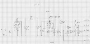
I just wanted to clarify something on you drawing. The two AVCC outputs are for AVCC-L and AVCC-R, correct? The top one looks like AVCL, and the bottom one just AVCC, but i realized it might just be your handwriting.
Thanks
John
Hi MrSlim,
Haven't talked for awhile. I think bih's drawing is supposed to have two AVCC outputs, either one of which can be used for either channel. May I ask if you are you asking because you are thinking about jumping into the fray and doing some mods yourself? If so, that would be great. Nice to have a really good DIY dac, don't know why more don't try it. Maybe they are waiting to see what other people say after finishing one. Like maybe, "is it worth the effort?" "how good does your's sound sound?" "how long did it take to finish it?" "which mods help the most?" etc.
Haven't talked for awhile. I think bih's drawing is supposed to have two AVCC outputs, either one of which can be used for either channel. May I ask if you are you asking because you are thinking about jumping into the fray and doing some mods yourself? If so, that would be great. Nice to have a really good DIY dac, don't know why more don't try it. Maybe they are waiting to see what other people say after finishing one. Like maybe, "is it worth the effort?" "how good does your's sound sound?" "how long did it take to finish it?" "which mods help the most?" etc.
Hey Mark,
I put the DAC mod project on the back burner for a bit so I could make some headway on another project I wanted to complete first, which really should take priority. I'm on vacation fror a month out of the country, but brought some of my "toys" with me to play with (a couple of arduinos and the boards for an arduino I2C controlled relay attenuator and selector for a BPBP) to dig into the programming, when we take a break from the sun and the sand. I just caught up with about 20 pages of posts, checking to see if anyone has gotten as far as doing up board designs for any of the off-board mods(the AVCC supply and I/V output circuit)
I have ordered some of the bits and pieces for this project (a 4137 SRC board, Clock Chip) and have a good power supply, but I won't be making any forward progress on it for a few weeks at least so I won't have anything to share there for a bit yet.
In the mean time, I have an idea about how I might be able to contribute, but I'm going to reserve comment for now until I have something to share.
In the mean time, I have been also collecting the parts for a board that DimDim created for use in his TFT HiFidunio and Universal Signal Isolator Shield projects, that may ease the path for accessing the 9038Q2M registers. Since the Q2M is in the same family as the 9038Pro, I'm hoping that the register set is equivalent. Anyway, I expect the code will be useful regardless
Last edited:
Nothing is obvious to me mate, as a complete beginner 😂
I was thinking about your instructions for building a DAC. Maybe some sort of "Jargon Buster" for people like myself who are starting out? There are lots of acronyms and terminologies that I'm struggling to understand. I guess it depends on how basic you want to be and if you want to appeal to novices, but I know I would find that most helpful.
Also, a basic modular breakdown of what needs to be built, would be very beneficial. It's a little daunting following this thread, which is excellent information, but difficult to piece together when you're starting from scratch.
Just some suggestions 😊
Alex,
I have been doing this so long I don't even know what someone would consider to be jargon. dac? ground plane? AVCC? Arduino? Arduino shield?
Why don't you make a list of ten jargon terms you would like clarified to start with, and I will try to clarify?
If that doesn't work maybe we could try a phone call sometime?
Regarding dac modding, what 'needs' be built is as much or as little as you want. What is the most you could 'build'? What would I recommend? I mean, I think you probably understand you should build an output stage board and an AVCC board? You mean beyond that? You mean what do you need to build to build those, or how to build them? I truly need more hints about what your request is. Remember, I don't know you, we never met, never talked, I don't know your background, educational level, etc? Where are we trying to start from?
Have you read or tried to read all the materials at the ESS downloads page? ESS Technology :: Downloads
Do you know how to read schematics? Know how to read a data sheet?
ASIDE: By the way, I just looked at your public profile to see if any clues there, and see you state you are a drummer which is also an interest of mine. Be interesting to talk about that sometime, but can't get too off topic in this thread. Anyway, profile didn't give me a clue about electronics background.
Last edited:
Hello Markw4! Congratulation to your successfully developed and built through-hole-board modification!
Can you already compare to the smd mod regarding SQ of different filter type? How about temperature of opamps? Do they also run hot with the new design?
Can you already compare to the smd mod regarding SQ of different filter type? How about temperature of opamps? Do they also run hot with the new design?
Mark,Not really, IMHO. It has a lot of problems too and will probably end up costing even more to make right. Cheap, low-cost circuitry, and cheap parts except for maybe the name-brand chip. Those guys are getting their costs down as low a possible because they operate in a very cost-sensitive market. Sometimes buyers will chose one seller over another based on a 1-cent price difference. The board you reference is made as cheaply as possible and still make people think it is worth more and a good deal. Maybe it is a good deal, in fact, but not high-quality, and not easily made into high quality.
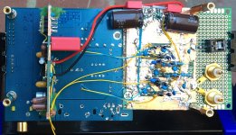
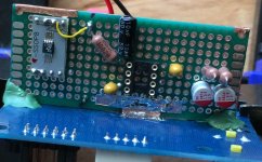
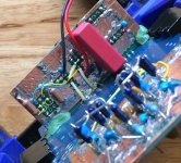
Regarding how to do it, I have posted photos of one way a few times. Don't remember what the posts were. Guess I can do it again. Click on the little white X in the lower left corner to blow up to full size or download and view in full size on a PC.
I also added a picture showing how to set the output sample rate for Windows from the sound settings in the control panel. Unfortunately, unless you have ASIO drivers for a sound card that is not the default sound device card, Windows will resample your audio to whatever that setting is and do a poor job of it. If you want to hear it unaltered you will need to reset it to match the sample rate of whatever file you are trying to play. When testing DAC operation, setting it correctly is mandatory or the exercise is probably a waste of time and even worse misleading. Macs do this type of thing too, maybe Linux.
Also, BTW, the power supply shown in the one photo is gone, as is one of the headphone amp options. The headphone amp shown is a modified $32 ebay special and pretty good. You need something you know is good enough to hear and judge DAC sound quality.
The other board is a TI SRC4392 upsampler board available from China for about $60 and worth it. Doesn't need modding to do what it is intended to do but may end up getting modded for this last bit of testing I am doing.
I haven't read this entire thread yet, so may have missed it. I have the exact same version of the Smpcb controller that you are using. I've tested Toslink and that works fine. I've never messed with I2S, but would like to get it to work as well.
I believe I properly matched the Pi pins to the Smpcb I2S inputs correctly. What is the next step? I'm just experimenting at the moment. No need for customization yet. 😉 Do I need to get Linux loaded and a Volumio to test?
Thx,
- Home
- Source & Line
- Digital Line Level
- ES9038Q2M Board