HI,
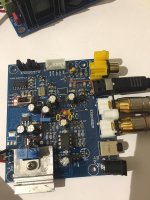
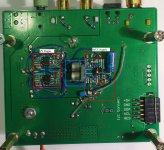
1) in the attached picture you can see that I removed the 47uF CAP near to the OPA in between the 2pcs 2k2 resistors (red marked place)
2) the common point of the 2 pcs 2k2 resistors were connected to the real ground
Basically this modification is NOT compulsory, since the voltage devider do almost the same, but the real ground is better as the virtual.
(You can also remove the 2 pcs yellow marked resistors, but if you are lazy not necessary)
Since it is not a compulsory modification for the simmetric PSU, please do the suggested move only if you double checked.
And do only after the modification Mark suggested.
Attachments
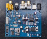
@babolcs, there is a bias network that biases the non-inverting opamp input DC voltage to 1/2 way be between the positive and negative power rails. That way if the negative supply is at ground or at -12v or-15v the bias will always be midway. I have outlined the bias network part of the board in a red rectangle in the picture below.
Also, if using a dual rail power supply I would agree that real ground would be better than virtual, since AC grounding at the node is accomplished with one or more capacitors. The node can be grounded in that case which will bypass the capacitors.
Also, if using a dual rail power supply I would agree that real ground would be better than virtual, since AC grounding at the node is accomplished with one or more capacitors. The node can be grounded in that case which will bypass the capacitors.
Attachments
Last edited:
@babolcs, there is a bias network that biases the non-inverting opamp input DC voltage to 1/2 way be between the positive and negative power rails. That way if the negative supply is at ground or at -12v or-15v the bias will always be midway. I have outlined the bias network part of the board in a red rectangle in the picture below.
Also, if using a dual rail power supply I would agree that real ground would be better than virtual, since AC grounding at the node is accomplished with one or more capacitors. The node can be grounded in that case which will bypass the capacitors.
Yes i told exactly the same with other words
")
Yes i told exactly the same with other words
I see, I think we cross posted.
Apologies if these questions have already been asked, but trying to find specifics in this huge thread ain't easy!
1. Is it a sensible, simple upgrade to swap the socketed op amp on this board for a better one?
2. There are 8x 100uf caps and 2x 47uF caps, all cheap electrolytics, is it a worthwhile upgrade to replace them with good ones such as os cons?
1. Is it a sensible, simple upgrade to swap the socketed op amp on this board for a better one?
2. There are 8x 100uf caps and 2x 47uF caps, all cheap electrolytics, is it a worthwhile upgrade to replace them with good ones such as os cons?
1. Is it a sensible, simple upgrade to swap the socketed op amp...
2. There are 8x 100uf caps and 2x 47uF caps, all cheap electrolytics..
The socket is a diversion the designers seemed to put there to help sell boards to customers who don't know much.
There are some specific power supply issues that need to be addressed, but they are not primarily due to problems with the existing electrolytics.
To make a difference with the board you can start to hear and that will make you happy you are really doing something, you need to fix the AVCC power supply and fix the output stage from voltage mode to current mode. That is what most of the stuff I mounted on the bottom of my modded board is for. Do that and you will have your first big WOW! moment. (also need to redo the circuitry around the opamp socket on top to make it into a differential summing stage for the I/V stages, or find some other place you would like to put that circuit function.)
If you have read the ESS document I mentioned as being most important on their download page, that has most of what you need to know in it. You just have understand what it means you need do. They are not kidding when they say to use certain circuits and components (excepting Abraxalito suggested scaling some filter values which shouldn't hurt and might help with opamp loading. I will admit I also deviated a bit around that part of the circuit with good results, so I did not actually test that part of one of the circuits as shown in the document).
What you need to think about is how to lay out an AVCC power supply using the exact types of opamps, capacitors, resistors, etc., as recommended) And do the same for the I/V and differential summing. When I built the summing circuit I did not include all the filtering which might protect an amplifier and speakers downstream from some HF junk that would be better if it were not there. So, I would recommend the filtering using C0G caps and high quality, tight tolerance thin film SMD resistors, and the suggested scaled values are probably what I would use.
Unfortunately, there is no easy way to make satisfactory improvements by lesser means. Sorry. If it looks too daunting maybe best to stop now. Otherwise, if you think you are up for it then you should probably be working out how you want to do it. If you would like to sketch out a schematic of what you propose to build and draw how you are thinking of laying it out, please post them here and we will be happy to take a look and let you know if we find anything that could be an issue. That way you should be well prepared when you are ready to start.
EDIT: Also, I would probably also suggest if you haven't built anything with SMD parts, that maybe you find a scrap board with SMD parts you can remove and replace for practice, or maybe get one of the SMD practice soldering kits from ebay with a little pcb and some parts to solder. It helps to have some small diameter solder like .3mm 60/40 and maybe some 63/37 for when you want to avoid melting higher temperature solder. There are also youtube videos with helpful info if one is so inclined.
Last edited:
It does sound a bit daunting, but that is largely because I've never done anything quite like this before, with guidance I reckon I can do it.
My plan is to first build a good PSU for the board, get it running and then make some upgrades and add an output stage.
I have a few soldering irons, but I think I'll need to buy a finer tip for one of them as none of them have a very fine tip and I'm used to soldering fairly large connections, so your suggestion to practice first is definitely appropriate for me.
What does AVCC stand for?
I'm still waiting for some of the parts I ordered to arrive, when they do, I shall be posting pictures of how I intend to lay them out inside the enclosure and getting advice at every step of the build.
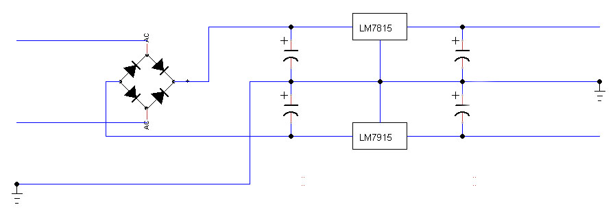
I've been learning to use TinyCAD and drew this layout for a simple PSU for the DAC board, do you think it will suffice or do you think I need to add more caps after the regulator?
My plan is to first build a good PSU for the board, get it running and then make some upgrades and add an output stage.
I have a few soldering irons, but I think I'll need to buy a finer tip for one of them as none of them have a very fine tip and I'm used to soldering fairly large connections, so your suggestion to practice first is definitely appropriate for me.
What does AVCC stand for?
I'm still waiting for some of the parts I ordered to arrive, when they do, I shall be posting pictures of how I intend to lay them out inside the enclosure and getting advice at every step of the build.
I've been learning to use TinyCAD and drew this layout for a simple PSU for the DAC board, do you think it will suffice or do you think I need to add more caps after the regulator?
Attachments
Maybe better to start off with LM317 and LM337 supplies for positive and negative. Make then adjustable up to +-18v. That way you could still use it later if you want to use post regulators. Or just buy a cheap board like that from ebay. You can also get them as fixed regulators and they are I believe later and better than the old ones you are thinking of. If you look at the data sheets for each one it shows you application circuits with everything there you would need. For rectifiers, it is good to use soft recovery diodes of some kind. Otherwise you can end up with some HF noise coming out of the power supply above the frequency the regulators can effectively smooth out. You could google soft recovery rectifier or look at devices like Hexfreds as one type of example. You might want to check the data sheet of any devices you are considering to see what the forward drop is. The transformer will need to be sized to allow for that.
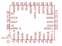
In the ESS document there is a schematic for AVCC supply. There are two pins that should each have their own supply. It is a super critical reference voltage used by the dac that has zero PSRR so you need to make the supply the best you can and as close to the pins as possible. Some of the pictures and the pinout for the dac show where the pins are.
There is also a voltage divider and filter you need to make for each AVCC supply. It is shown in the schematic on the ESS downloads page. It is two 10k resistors to make a divide by 2 and with a 10uf electroytic to ground connected to the output of each one to make an output filter. The divided voltage is called the reference voltage in the schematics or Vref.
Last edited:
I must have had a brain fart when I labelled that diagram as I bought an LM317/LM337 board:
LM317 LM337 AC-DC 5V 12V Adjustable Voltage Regulator Regulated Power Supply | eBay
LM317 LM337 AC-DC 5V 12V Adjustable Voltage Regulator Regulated Power Supply | eBay
I wonder why it says 5v and 12v? Hopefully, the caps and rectifiers are rated high enough to allow for at least +-15v. If the adjustment pots don't go that high, it is easy to fix with a resistor or new pot.
Maybe helpful to look at the data sheets for the regulators if you haven't. This project is probably advanced enough that some some data sheet reading will be appropriate. If any questions about what is in data sheets, this is probably a good place to ask.
Do you already have a transformer in mind?
Maybe helpful to look at the data sheets for the regulators if you haven't. This project is probably advanced enough that some some data sheet reading will be appropriate. If any questions about what is in data sheets, this is probably a good place to ask.
Do you already have a transformer in mind?
I'm quite happy to change the components on that board if it won't adjust upto 15-18v.
Transformers, I was hoping to be able to use one of the ones I already have which are two taken from Cambridge Audio CD5s, one from a Cambridge Audio D100 and one from a Sony TA-FE370 amp. I need to find out what their outputs are.
If none of them are suitable, I'll buy a toroidal.
Transformers, I was hoping to be able to use one of the ones I already have which are two taken from Cambridge Audio CD5s, one from a Cambridge Audio D100 and one from a Sony TA-FE370 amp. I need to find out what their outputs are.
If none of them are suitable, I'll buy a toroidal.
Do you know how to find the output voltages? Roughly speaking the AC RMS voltage into a matched resistive load is about what you could get out at DC, less rectifier and regulator drops. At the other extreme the unloaded peak output voltage is the highest you could get. Depending on the transformer current capacity that range can vary quite a bit, which means the power supply components need to be rated to handle it, including the heat sinks. In addition the transformer needs to be able to supply enough current for the load. The negative load is small, but all the digital circuitry on the DAC board runs off regulators that drop it down from the +15v. That positive rail current draw also goes up as playback sample rate goes up. You probably need at least 150mA of +15v just to get up to 192kHz. However, if you decide to run all the +5v stuff from a separate supply then the +15v current draw is pretty low. Obviously, the regulators should be able to handle the current easily so long as they have enough heat sink. If you have a small transformer it may or may not be able to supply enough current for what you will need. If the transformers are unmarked you could try running them into a test load and see how warm they get. That's probably a good clue if you are pushing it. Also, if there is too much voltage droop with current. A small variac can be handy for judiciously adjusting the voltage up into a test load to see how it looks.
Last edited:
I was planning to stick my digital multimeter on the output wires to find out what they are pumping out, certainly the large one from the Sony amp will have more than enough current, the smaller Cambridge Audio ones I expect will have too as they are from CD players which have quite a lot more electronics to power than this dac board plus a transport mechanism to power.
That said, I will certainly follow your advice and make sure whichever I use isn't getting hot.
I'm quite happy to use more than one transformer if needed, I'm already going to need at least two as the output stage will be powered separately.
That said, I will certainly follow your advice and make sure whichever I use isn't getting hot.
I'm quite happy to use more than one transformer if needed, I'm already going to need at least two as the output stage will be powered separately.
the output stage will be powered separately.
Best to make sure AVCC is powered from cleanest analog supply you have. Possibly VCCA and or the clock too. Also, need to be sure power supplies are appropriately cycled at the same time or in the specified sequence needed by the DAC.
To get a better idea of how I did it, the AVCC and I/V circuits are in red boxes. The little red circles in the AVCC box are where the AVCC supplies connect to pins at the bottom of the AVCC filter caps on the top of the board. They go right into the DAC pins, so distance is as close as I could reasonably get it.
The blue box is the two Vref voltage dividers and filter caps. The 10k thin film SMD resistors are mounted vertically on that little piece of circuit board material that the filter caps are mounted on. So, you can't quite see the resistors as the picture shows an end view of the little circuit board.
Attachments
A valve is active crap, unfortunately. If you get rid of all of it you wont have any dac at all.
Not sure where some information comes from but opamps used for DACs have much, much lower distortion than any valve. Valves are good for adding a little distortion, exactly what gives Lampizator its special sound. It is a little distorted, but a kind many people seem to like.
Ok, I'm officially out. I'm not a tube fanatic but they are far more than just 'distortion' generators. I can't believe it's 2018 and this kind of dismissive reductionism is still being peddled.
- Home
- Source & Line
- Digital Line Level
- ES9038Q2M Board