Markw4, your notes are useful! I guess there has to be extensive modification to achieve decent sound, personally I am not sure if I could follow those modifications, so maybe better off searching for tested/reviewed alternatives. At first glance it seemed that is a good design, maybe too much silicone for nothing...
That is the very issue I ran into and then moved to a different DAC board. These cheap boards need substantial amount of fabrication to get sounding decent. None of these required boards are easily available...save for one, maybe the OPAMP AVCC supply, see an earlier thread where you could use a 5532 preamp board from Ebay to make one up. A coupel bucks and some changes in components and you have it. BUT then comes the IV stage with three op amps. I searched and searched and there was nothing that I could easily reconfigure.
So I went with another DAC and I am now happy as ever about the sound I am getting. It will cost more but less effort is involved and if anything I can tell you, it works. Moving from 9038Q2M to a 9028Pro board
For most of the discussion, the reference DAC is (by Markw4) the Benchmark DAC3.That is the very issue I ran into and then moved to a different DAC board. These cheap boards need substantial amount of fabrication to get sounding decent. None of these required boards are easily available...save for one, maybe the OPAMP AVCC supply, see an earlier thread where you could use a 5532 preamp board from Ebay to make one up. A coupel bucks and some changes in components and you have it. BUT then comes the IV stage with three op amps. I searched and searched and there was nothing that I could easily reconfigure.
So I went with another DAC and I am now happy as ever about the sound I am getting. It will cost more but less effort is involved and if anything I can tell you, it works. Moving from 9038Q2M to a 9028Pro board
Benchmark DAC3 HGC D/A preamplifier-headphone amplifier | Stereophile.com
It is 20 times of the cost of the MShow ES9038Q2M box I have and 10 times the cost of your ES9028PRO. What can we expect?
Stereophile review on DAC3 said:When (Benchmark) released the DAC3's predecessor, the DAC2, they published an Application Note titled "Benchmark DAC2 vs. DAC1—Is There an Audible Difference?" Their answer: "The noise and distortion produced by [the DAC1 and the new DAC2] is well below audibility in normal operating conditions. Nevertheless, there are some situations where the DAC2 can provide an audible improvement."
When we start with a cheap Chinese DAC board, my goal is not to achieve the DAC3 sound quality. It would be if I can. It is still wonderful to make the noise and distortion well below audibility in normal operating conditions.
I am now happy as ever about the sound I am getting. It will cost more but less effort is involved and if anything I can tell you, it works.
Now, we have a ES9038Q2M based box with I/V output on the market. How well does it sound compared to the ES9028PRO board?
I appreciate the inspiration provided by Markw4. He is the one who pushes us to get here.
Last edited:
At least we hope the new board Mikett is working on will turn out to be as good as we know how to make the board original board in this thread.
Regarding the new Bluetooth Q2M board I just got and have been working on, I just got around to taking a good look at the grounding scheme on it. I think I already mentioned that the IV and differential output stage area of the board has no ground plane, contrary to what ESS recommends. It only has one thin trace running down the length of the side to do all the signal and power bypass grounding. I though I might be about to improve that then I realized the ground path back to the Q2M chip for IV signal returns was a nightmare mess. It runs back under the +-14v switching supplies, around the other corner of the board, up though about 3 vias to a short strip on top of the board, then back down though a couple of vias to return to Q2M from the completely opposite side of the board. No wonder it sounds bad and distorted with switching noise.
According to ESS, that is supposed to be a direct line-of-sight ground plane from the Q2M to the IV stages with no interruptions of ground plane by cross traces. Wow, this is much, much worse than a cross trace interfering with line-of-sight. Don't know what I am going to do. Have to think about it it. Don't see any solution except to redo the ground plane scheme under the board, abandon the on-board +-14 switching supplies, and use external supplies for that power. What a mess.
While I was thinking about that, it occurred to me we may not be clear if Mikett's new 9028PRO board has ground plane under the IV and differential sections with line of sight back to the 28PRO chip. Also, not sure about the film caps in the IV stages of that board, since I have had to remove the film caps and opamps from the bluetooth Q2M board while trying to figure out if the IV output can be successfully redesigned to sound acceptable (which, if it is reasonably possible, will probably involve a fair amount of fabrication, not to mention a clock upgrade and new AVCC supply it will need).
Unfortunately, I only feel confident right now that we have a proven roadmap for the old ES9038Q2M board in this thread that has been vetted with measurements and direct DAC-3 listening comparisons. That is kind of unfortunate from the perspective as Mikett points out that to get there requires a lot of fabrication work.
Maybe when the 28PRO board is done we could find some way to measure it. Actually, I think the moderator Anatech, who has measurement equipment, might not be too far from where Mikett is, location-wise that is. Maybe something could be worked out somehow with them, don't know. Have to wait and see what might be possible, I guess.
Last edited:
Regarding the new Bluetooth Q2M board I just got and have been working on, …………… the ground path back to the Q2M chip for IV signal returns was a nightmare mess. ………………. No wonder it sounds bad and distorted with switching noise.
 Still no easy path to get I/V for the ES9038Q2M board.
At some point one has to grapple with some kind of compromise. Even fabbing will introduce compromises with the leads off board. Remember, one aspect of compromise is determining what one wants to achieve. One of those must haves is a decent looking piece of equipment at the end of the project for me. That was cast in granite. The early projects I did in the late 70s, looked like DIY stuff. In the early 80s, those days were gone for me. It had to look decent. That required I study what my end goals are, ACCEPT sometimes you can't have everything. That landed me to the board I chose.
There was another one that provided separate leads for AVCC L&R via ADP 150s but the case for it was too small to hold additional power supplies. Then there was another one that was about twice what I paid and it included two separate LT1763s and the IV section was true dual mono but there was no case...So despite it having more potential, I dismissed it.
In all of this at the back of my mind was that if I failed in this attempt I'd swallow the losses,then I would indeed stretch and purchase the DAC3. Right now, I've put that off until they come up with a better support for DSD and that means perhaps the next gen. These DACs are getting obsolete quickly so I'd rather wait for better maturity and then consider. My feeling is that ESS next PRO chips will be better integrated into what makes it work best but the cost of the chip itself will increase. They will not allow a mobile solution to get close to the Pro chip unless there is something in the works. So any DIY DAC getting close to 1/4 to 1/3 the cost of the DAC3 was a no go for me. I'd just pick up a new or used DAC3 and it would represent much better value because it is worth something in resale even after 3 years.
I even considered a twisted pear Buffalo III offering but no case and in the end I would have spent quite a bit...so for ME, I would have tended to go with a retail unit even if it costs more again for the resale aspect.
And yes there is one more thing, in 3 years I will probably be unable to build myself something better because of my age. So this represents possibly one of my last DIY projects.
And if you followed what I was doing, I was ready to fab a 3 op amp IV and AVCC via 2 dual LME48720 for this cheap board , until I saw the single op amp circuit and thought that it was so simple I'd give it a try. and then poof. Also keep in mind that fabbing is one thing but when we get to the levels that Markw4 is targetting, how you run the off board wires and where you run it and what you use kicks in and the board is sensitive to that. Someone possibly more needs to follow what he did and verify that it can be replicated. There are so many variables along this path...it's close to completely remaking the DAC circuit.
I say this because something as simple as a power supply regulator like the Super Reg needed lots of tweaking over years not just for performance but stability as well. When I built my Sulzer borbely power supplies integrated with Richard Marsh's head amp and Leach Fet preamps in the 80s all true mono channels, the stupid PS was never stable. I could only get it stable if I throttled back to TL071s. I roughly followed the same pattern that was originally used but not close enough. In the end I had some new boards made up where I copied the initial board layout and it ran perfect with 5534s. Just my experience when you shoot for high performance and why I don't always like fabbing boards. Been there as an amateur. BTW, the same PS I am using was used to modify a Philips CDB 582...running the TDA1541.
Hence why I crossed to the 9028PRO side.............
Last edited:
These DACs are getting obsolete quickly so I'd rather wait for better maturity and then consider.
Don't know about that. I kept my DAC-1 for a decade. When I decided to get a DAC-3 after that 10 years I saw I could sell the DAC-1 in the range of 1/2 to 2/3 of what I paid for it. I ended up selling it at a very low price to an old friend who was using a Lynx2 sound card, which is often considered serious professional level recording interface. I don't think he really believed me when I told him how much better the DAC-1 was, but he bought it from me anyway because the price was so low he could turn around and sell it without any risk. He was so skeptical he left it sit for about three months before he decided to go ahead and give it a try. He contacted me right after that to tell me he was very happily surprised and couldn't believe how much better it sounded than the Lynx (which it does).
Moving along with predictions about future DAC technology vs what we have now, reason DAC-3 probably doesn't support higher speed DSD could well have to do with the physics of quartz crystals, not fast changing DAC technology. You can get MUCH lower jitter quartz crystal clocks that run at 30MHz than you can for 100MHz. If you want the good sound of that very low jitter then you have a choice to make. If you mostly listen to CDs and DVDs then then you are probably better off with the lower-jitter clock and skip high sample rate DSD that needs a faster, higher-jitter clock. That trade-off decision may not change very soon at all. Quartz clocks are likely going be with us for foreseeable future.
Approprite HPA for testing
Hi Mark, All,
I built the 49600 based HPA. The DC servo based version which is slightly more complicated but proves no DC on the output. Comparing to my Lehmann (Class A) HPA basically it has slightly clearer voice. The difference is minor, but some distortion from the middle range disappeared.
Sz.
Thank you. Just to be aware they are fast and can oscillate easily if care is not taken to use a ground plane and proper decoupling. Just a word to the wise. Somewhere I wrote some things about what I found out when modding my HPA. Think it may have been back here: http://www.diyaudio.com/forums/digital-line-level/314935-es9038q2m-board-63.html#post5402398
Also, it started as one of these, but I found I had to do some work on it: 1PCS LME49720NA+LME49600 headphone amplifier KIT | eBay
If you would like to talk about it some, be happy to.
Hi Mark, All,
I built the 49600 based HPA. The DC servo based version which is slightly more complicated but proves no DC on the output. Comparing to my Lehmann (Class A) HPA basically it has slightly clearer voice. The difference is minor, but some distortion from the middle range disappeared.
Sz.
...some distortion from the middle range disappeared.
Very good, low distortion is what we need for comparing DAC mods.
When you say you you built the DC servo version, did you buy a bare PCB and populate it, build it from scratch, or something else? Do you have any pictures (others may be interested too)?
The manufacturer/seller claimed SNR at 123dB and 20-20K band distortion of 0.00006%. There is no doubt some level of marketing exaggeration. It would be nice to see some real world measurement by an independent reviewer.Regarding the new Bluetooth Q2M board I just got and have been working on, I just got around to taking a good look at the grounding scheme on it. I think I already mentioned that the IV and differential output stage area of the board has no ground plane, contrary to what ESS recommends. It only has one thin trace running down the length of the side to do all the signal and power bypass grounding. I though I might be about to improve that then I realized the ground path back to the Q2M chip for IV signal returns was a nightmare mess. It runs back under the +-14v switching supplies, around the other corner of the board, up though about 3 vias to a short strip on top of the board, then back down though a couple of vias to return to Q2M from the completely opposite side of the board. No wonder it sounds bad and distorted with switching noise.
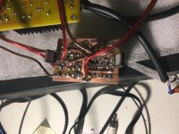
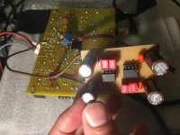
I ordered a pcb but since the delivery time is expected 2 month (eBay) I decided to draw a pcb. I’ve forgotten to mention that I could realize a complete DC coupling - so no cap at all in the signal path.
I used the protection circuit of the Lehmann. So likely small chance to get in trouble.
And I would mention the amazing packaging of the 49600. (Ordered from mouser - small box- anti static sponge inside)
ok here you are the pictures. The pcb itself is not very nice. I started to plan it with KiCad but finally drew manually not having laser printer at home to be able to print to a transparent film.
Attachments
What was the first impression of the SU5's SQ? How would you compare it to the board that you have been working on before you started the mod?@keilau , Too late for mine to be measured since it is in pieces.
The Chinese manufacturers seem to take numbers from chip data sheets and quote them without any regard for what they actually mean.
I know you are not impressed by the SU5. But does the I/V do any good to the SQ? Or it does not matter until you get the PS right?
@babolcs, some of those film caps might be good up to 1MHz or more, but LME49710 have GBP up around 55MHz. Unlikely film caps are good for bypass with those. I use X7R ceramics and 10uf tantalums right at the pins to the ground plane. Same for bypassing LME49600. They can oscillate at many MHz and you might not know it if you don't have a good enough scope. Less likely to be a problem if a well designed kit is used, but for total DIY hard to say without checking.
Last edited:
What was the first impression of the SU5's SQ? How would you compare it to the board that you have been working on before you started the mod?
The original board that I modded at first sounded so bad it was what I would call un-listenable.
The SU5 is not as bad. I would not quite say un-listenable, but one would have to be pretty tolerant of distortion to listen to it. For me, like I said, it is fix it or throw it away decision. It is definitely worse than an average car radio or something, seems to me anyway. I thought the switching power supply might have been the worst of it, which is why I tried the LiFePO4 batteries. Better, but still not right was for certain. Maybe the long, strange ground path back to the DAC chip was a lot of the problem, but then I remembered that basically, one has to get every little detail right to have a chance at getting close to -120dB distortion. Still too far away so I realized it was not going to be a quick and easy fix. Everything would have to be made right to get it close to competitive with the first Q2M DAC after it was modded. Lot of work ahead I am afraid. Not only for the IV and switching power supply, but also AVCC power and clock. After all that it might be okay, but I doubt it would ever be able to get up to 960kHz and DSD512 like the other DAC because I don't think the CPLD chip will go that high, and everything goes through that chip.
Last edited:
@babolcs, some of those film caps might be good up to 1MHz or more, but LME49710 have GBP up around 55MHz. Unlikely film caps are good for bypass with those. I use X7R ceramics and 10uf tantalums right at the pins to the ground plane. Same for bypassing LME49600. They can oscillate at many MHz and you might not know it if you don't have a good enough scope. Less likely to be a problem if a well designed kit is used, but for total DIY hard to say without checking.
Earlier I eliminated all th x5r even from the power path since it seemed to me that it bring some strange distortion in the sound. but I will try again directly at the legs of the ICs.
In the sound path definitely can not be applied since it has some voltage dependencies. It is in the ESS guide. (But as I understood you haven’t considered this case at all)
Hi level oscillation would generate some heat so it is not in the circuit but you are right I can’t see the low level ones.
(Unfortunately the scope budget was not approved by my wife
since I do not want to cheat I have the wait for a while).Anyway I frankly don’t know what to apply in the negative feedback part. Although the non x5r dielectric lower cheramic caps doesn’t have the voltage dependency but here in the dc servo integrator where you need 1uF... ???
Last edited:
If strange distortion then maybe best to wait. If the 49600's are getting too warm for no reason then I would be concerned about oscillation. If they are reasonably cool, then maybe okay for now. Hard to say. Sounds like we agree on that. If implemented correctly, you should get about -105dB distortion from the headphone amp. It cannot be -120dB, but by the same token it should not be -97dB either.
Also, if the headphone amp is working correctly and there is any remaining problem with the DAC then it should be audible. But, you might not know what it should sound like if you do not have some reference somewhere to compare with.
If you know somebody with a good 24-bit sound card then you could try some measurements of the sound card itself and then of the DAC. Don't suppose there are many resources available where you are? But, you must have a computer or you wouldn't be online. Maybe you already have a 24-bit sound card?
Also, if the headphone amp is working correctly and there is any remaining problem with the DAC then it should be audible. But, you might not know what it should sound like if you do not have some reference somewhere to compare with.
If you know somebody with a good 24-bit sound card then you could try some measurements of the sound card itself and then of the DAC. Don't suppose there are many resources available where you are? But, you must have a computer or you wouldn't be online.
Maybe you already have a 24-bit sound card?
Last edited:
I have an SB 1240 external which theoretically classified as audiophile.If strange distortion then maybe best to wait. If the 49600's are getting too warm for no reason then I would be concerned about oscillation. If they are reasonably cool, then maybe okay for now. Hard to say. Sounds like we agree on that. If implemented correctly, you should get about -105dB distortion from the headphone amp. It cannot be -120dB, but by the same token it should not be -97dB either.
Also, if the headphone amp is working correctly and there is any remaining problem with the DAC then it should be audible. But, you might not know what it should sound like if you do not have some reference somewhere to compare with.
If you know somebody with a good 24-bit sound card then you could try some measurements of the sound card itself and then of the DAC. Don't suppose there are many resources available where you are? But, you must have a computer or you wouldn't be online.
I will check the parameters. (Naturally I have som PCs at home
)I will check the params of it.
Anyway The current mod DAC has much better voice.
If the A/D in a sound card is good enough, you can use it directly to look at the DAC performance. Probably the sound card you have isn't good enough so you would need to make a notch filter, such as at 1kHz.
Then you can play a fairly loud 1kHz tone though the DAC, then run the output of the DAC into the notch filter, then go out of the notch filter into the A/D and look at the signal with an FFT. Even will a fairly mopdest performance 24-bit A/D it can work okay if a clean notch filter is available.
At one time there was a diyaudio thread to make a Hall notch filter. It can give about 40dB attenuation at 1kHz which is good enough to mostly leave whatever harmonic distortion the DAC may produce from the 1kHz test signal.
There are various programs that can be used for that. A pretty good and pretty powerful freeware program is Spectrum Lab, but it takes some reading the manual and getting used to as it has a lot of options: DL4YHF's Audio Spectrum Analyser
If the A/D in a sound card is good enough, you can use it directly to look at the DAC performance. Probably the sound card you have isn't good enough so you would need to make a notch filter, such as at 1kHz.
Then you can play a fairly loud 1kHz tone though the DAC, then run the output of the DAC into the notch filter, then go out of the notch filter into the A/D and look at the signal with an FFT. Even will a fairly mopdest performance 24-bit A/D it can work okay if a clean notch filter is available.
At one time there was a diyaudio thread to make a Hall notch filter. It can give about 40dB attenuation at 1kHz which is good enough to mostly leave whatever harmonic distortion the DAC may produce from the 1kHz test signal.
There are various programs that can be used for that. A pretty good and pretty powerful freeware program is Spectrum Lab, but it takes some reading the manual and getting used to as it has a lot of options: DL4YHF's Audio Spectrum Analyser
Thanks a lot.
I was also considering to use this soundcard for testing, but since I have 1 pcs I either use it a sound source or an analyser, so I didn't go into this direction yet. but I will think over again.
(basically I can create CD-s with test signals.) Thanks for the inspiration.
- Home
- Source & Line
- Digital Line Level
- ES9038Q2M Board