Be aware that THD performance will be in the range of -70 dB. This link shows typical ES9038Q2M measured performance without a proper I/V converter output stage: Measurements Of Generic ES9038Q2M DAC Board | Audio Science Review (ASR) Forum
If you instead use the I/V output stage in post #6944 you can get performance like what I posted in #6981.
So the power supplies are important but if you don't use the correct output stage with this DAC the results will be very poor.
Yeah, I can comfortably say there is a hell of a lot else happening in your build to put that woeful measurement down to being in voltage mode. it is fairly straightforward to get -105 -> -110dB THD (better is possible) in a well laid out voltage mode schematic. -70dB is a long way from what was possible with old ES9018PRO dacs i've played with. Hell, I got better with a couple onetics line traffos with passive IV in front and no effort to cancel DC currents. of course there were some unwanted euphonic non-linearities in addition, but still nowhere near -70dB.
The boards come this way stock (-70 dB range) as measured by others:Nothing to do with my particular build. Simply that is the design of the board that was recommended in this thread.
All I know is that I changed first the power supplies and then the output. Nothing else. The great big step change in the results were immediately after changing the output stage from voltage mode to I/V. (Not after changing the supplies.) Nothing else was changed in that step. Only stock voltage mode to I/V.
All I know is that I changed first the power supplies and then the output. Nothing else. The great big step change in the results were immediately after changing the output stage from voltage mode to I/V. (Not after changing the supplies.) Nothing else was changed in that step. Only stock voltage mode to I/V.
Both measured and audible. First I did work on the supplies (with measurements and about 2 weeks of listening) and then I replaced the voltage mode output with the I/V stage (with measurements and I have been listening to the I/V stage since then).
The supply work did improve both measurements and my listening impression. However the bigger step (in both measurements and listening impression) was from replacing the voltage mode output with the I/V stage. After only the supply work I was still seriously considering scrapping the board. Since replacing the voltage mode output with I/V output I have enjoyed listening to this DAC.
The supply work did improve both measurements and my listening impression. However the bigger step (in both measurements and listening impression) was from replacing the voltage mode output with the I/V stage. After only the supply work I was still seriously considering scrapping the board. Since replacing the voltage mode output with I/V output I have enjoyed listening to this DAC.
Nobody knows for sure when that will be. Could be more than another year. Maybe sooner if AKM can get some other fabs to make selected AKM parts. They say they are working on it, but no specifics yet.
I have heard that Renesas privides the part of their factory to AKM, and the production will starts at Feb/Apr.
P.S. Don't know, may be it is a fake news, too good to be true...
Hey guys 🙂
I have a question/problem regarding the ES9038Q2M. It would be really great if you could help me with your deep knowledge about this DAC.
I'm currently working on a project where I plan to use the ES9038Q2M for high snr sine wave generation. The data stream is generated by an FPGA and supplied via i2s.
I already found out that the DAC isn't operational using it's default register config and that you have to set Bit 7 or 6 in Register 14 in order to get any analog output. Kind of a strange design decision if you ask me, but ok.
At this point I would expect the analog outputs to ramp up to AVCC/2 after writing to register 14. However I only see them ramp up to ~730 mV, while AVCC/2 should be like ~1.65V. Do you have any idea why that is?
Also, after ramping up the outputs I don't see anything of my input data stream on the analog outputs so far. But it seems like the DAC is able to lock to my input data stream, because it will ramp up the analog outputs if I set Bit 6 of Register 14 - which means that the outputs will only ramp up when the DPLL is locked.
Any help would be greatly appreciated!
Greetings from germany, Simon
Hi Simon,
Lock status can be read from Register 64, Bit-0. At least there is no need to guess about that.
For troubleshooting purposes I would suggest to verify Lock before setting ramp-up in Register 14.
Beyond that, only a few things one might want to check come to mind at the moment:
* AVCC voltage is somehow being pulled down when ramp up is enabled.
* The output stage is somehow loading down the dac outputs.
* The power up sequence on page 49 of the data sheet was not correct.
If none of the above help, maybe we could think of some other things to try.
In particular, can't think of any register programming issues that are known to cause the symptom you describe.
If nothing else, maybe a bad dac chip?
Last edited:
Hi Mark,
first, thank you very much for your answer 🙂
I was sort of "guessing" that the DPLL is locked because I currently don't have any I2C read logic in my HDL design. I thought that I might not need that 😀 But now I will make sure that I can also read back register contents somehow. Maybe that will help me to debug my issues.
But from reading the manual, it seems like my outputs should ramp up to AVCC/2 regardless of the lock status if I set Register 14 Bit 7, right? So the lock status shouldn't be relevant for my AVCC issues, right?
Nope, I checked AVCC after ramp up. Rock solid 3.3V.
I do have an output stage with I/U-converter and differential-to-single-ended conversion based on the AD797. But for testing purposes I disconnected the output stage. So what I measure is the DAC output with absolutely no load on it.
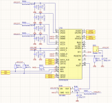
I have the reset on a jumper header and I manually set the jumper after power up of the board. So DVCC, VCCA, AVCC_L, AVCC_R and XI should be stable when the reset pin is set to high. There is also hardware debouncing on that pin. I attached my schematics.
Seems very unlikely. I got two boards and they both show the same behaviour.
Greetings, Simon
first, thank you very much for your answer 🙂
Lock status can be read from Register 64, Bit-0. At least there is no need to guess about that.
For troubleshooting purposes I would suggest to verify Lock before setting ramp-up in Register 14.
I was sort of "guessing" that the DPLL is locked because I currently don't have any I2C read logic in my HDL design. I thought that I might not need that 😀 But now I will make sure that I can also read back register contents somehow. Maybe that will help me to debug my issues.
But from reading the manual, it seems like my outputs should ramp up to AVCC/2 regardless of the lock status if I set Register 14 Bit 7, right? So the lock status shouldn't be relevant for my AVCC issues, right?
* AVCC voltage is somehow being pulled down when ramp up is enabled.
Nope, I checked AVCC after ramp up. Rock solid 3.3V.
* The output stage is somehow loading down the dac outputs.
I do have an output stage with I/U-converter and differential-to-single-ended conversion based on the AD797. But for testing purposes I disconnected the output stage. So what I measure is the DAC output with absolutely no load on it.
* The power up sequence on page 49 of the data sheet was not correct.
I have the reset on a jumper header and I manually set the jumper after power up of the board. So DVCC, VCCA, AVCC_L, AVCC_R and XI should be stable when the reset pin is set to high. There is also hardware debouncing on that pin. I attached my schematics.
If nothing else, maybe a bad dac chip?
Seems very unlikely. I got two boards and they both show the same behaviour.
Greetings, Simon
Attachments
Hi Simon,
I would try both ramp-up bits 6 and or 7 in Register 14. Personally, I am skeptical of things always working right at first so I would read them back for confirmation. However, as long as you see the outputs start to ramp when you command them to, then it seems like the dac is trying to do what it should.
The voltage ~730mV seems suspiciously suggestive of a small diode biased on fairly hard. Don't know why an output would stop at that particular voltage at is all. At this point I would probably want to measure AVCC currents at ramp-up to see if abnormal current flows. The datasheet suggests normal might be about 6mA, at least under their specified test conditions.
Regards,
Mark
PS: Regarding the schematic in your post, looks like it should work. However, I wouldn't especially want to use it for playing music. As a test signal generator it might work okay if low THD+N is the primary concern. If, say, something like sine wave phase noise were a critical issue, and if it didn't measure well enough to satisfy design goals, then I might try doing things rather differently.
Last edited:
I would try both ramp-up bits 6 and or 7 in Register 14. Personally, I am skeptical of things always working right at first so I would read them back for confirmation. However, as long as you see the outputs start to ramp when you command them to, then it seems like the dac is trying to do what it should.
Yeah, I don't feel like reading back those particular bits would make any sense at this point. The DAC clearly tries to ramp up the outputs to AVCC/2 on my command. I can also control the time it takes to do that by writing to Bit 4 to Bit 0 of Register 14. The only problem is that it doesn't reach AVCC/2.
Reading back registers might be useful later on for checking lock status, input selection and stuff like that. But I have the feeling that further steps make little sense while there is obviously something wrong with the analog outputs of the DAC. Seems to me that this should be solved first before I spend more time on working with this DAC.
The voltage ~730mV seems suspiciously suggestive of a small diode biased on fairly hard. Don't know why an output would stop at that particular voltage at is all. At this point I would probably want to measure AVCC currents at ramp-up to see if abnormal current flows. The datasheet suggests normal might be about 6mA, at least under their specified test conditions.
Those 6 mA that are mentioned in the datasheet seem to be correct. I roughly measured the current. The current smoothly ramps up to 6 mA during ramp up of the analog outputs. No signs of excess current draw during ramp up. My AVCC Buffer seems to work fine. AVCC stays at solid 3.3V during ramp up.
PS: Regarding the schematic in your post, looks like it should work. However, I wouldn't especially want to use it for playing music. As a test signal generator it might work okay if low THD+N is the primary concern. If, say, something like sine wave phase noise were a critical issue, and if it didn't measure well enough to satisfy design goals, then I might try doing things rather differently.
You are right, low THD+N is the primary concern for this sine wave generator. Well, to be honest, my biggest concern right now is just getting this thing to work 🙁 I'm pretty lost at this point. I got no idea about what could be wrong.
kozard,
Just for fun you might try setting your dac board inside a steel box. I use an old emptied out file server case. Don't even need to put the lid on to see if there is an audible difference, at least at my location. I find it helps if the solid side walls of the case are oriented to best attenuate the radiated EMI/RFI here, which tends to mostly come from the West, a huge and populated area.
The other thing I might suggest would be if you are using batteries for AVCC_L and AVCC_R. Batteries for that didn't sound very good to me when I tried it. If nothing else I would probably want to try LM317 regulators or whatever you have. Doesn't have to be ultra-low noise if the only purpose is to see if it sounds better than a battery.
Of course I understand you want it to be good enough so you don't have to scrap it, but if you have parts laying around that might make it better than the minimum acceptable, why not try it?
Last edited:
A more recent update from Reneas: UPDATE 2- Impact of the February 13 Earthquake in the Coast of Fukushima Prefecture on Renesas Electronics Operation | Renesas
Hey Mark (and all the others 😱)
I solved my issue. Turns out I'm an idiot. I didn't properly disconnect my I/U-converter stage from the DAC output. I disconnected the OP Amp, but I missed that it's feedback path was still connected to the DAC output. And obviously that was pulling down the DAC output to ~730 mV. After disconnecting it properly, the output ramps up to AVCC/2. Oh boy, that was a very stupid move.
I hope that I'm still allowed to ask any further question that I might have while working with the ES9038Q2M. I promise I won't be stupid again. 😀
From an insider, Renesas will manufacture only the standard auto related, the bulk of the business, products; the high end audio stuff (like the AK4499) are built in a special dedicated process that is not compatible with silicon foundries; outsourcing these processes is not an (economic) option.
I hope he is wrong.
Hi Simon,
Thanks for sharing the solution. Stuff happens, it happens to everyone now and then. Sorry your little problem will be preserved in a forum thread, is all.
Thanks for sharing the solution. Stuff happens, it happens to everyone now and then. Sorry your little problem will be preserved in a forum thread, is all.
In theory, I don't see any reason to be smaller than AVCC/2 (would lower the dynamic range) or over AVCC/2 (no real benefit). However, in practice, it is the op amp maximum output swing which dictates the offset voltage. For rail to rail op amps (like the superb THS4551 differential in/out) AVCC/2 is just fine; other op amps may need raising the offset to account for the limited voltage swing toward ground.
So, in a nutshell, it's a matter of the op amps used in the IV stage.
Cheers for fleshing out on the point Regarding rail voltage and how close you can swing to the rails, with your chosen opamp. I had made a longer post, but was self conscious of prattling on and then I had a power outage. (not inferring you are prattling on).
Yes, I agree, higher AVCC is of possibly dubious, or at least application specific benefit. It depends on whether you want, or can use the extra gain; but of course there are many ways to achieve gain. Its a left-over from my experiments with 9018 and ive only ever used a touch extra, not the crazy and unnecessary high >4VDC AVCC some others on the forums ended up with. I will be revisiting it with the 9038, at my usual 3v6, but whether it stays or not remains to be seen after measurements. Indeed, always loved the THS series chips
InspectorGadget,
All that stuff has been discussed in this thread before. Many folks at some point focus their thinking on choosing opamps, and on calculating stuff they know how to calculate.
Most of those things aren't the tricky part of making one of these dacs sound good. A lot of it is related to management of RF noise mixed in the audio at the dac chip outputs. That puts a lot of constraints on opamp choices and output voltage swings. Not to mention there are other areas of dac design that need attention.
The good news is that many solutions are already known, but there is some more work that needs to be with output stage filtering between the I/V stage and the differential summing stage. Layout probably plays a role there too.
If anyone has a fast digital scope and a spectrum analyzer, that might make the lab work part of the problem solving much easier...
Last edited:
Many folks at some point focus their thinking on choosing opamps, and on calculating stuff they know how to calculate.
Most of those things aren't the tricky part of making one of these dacs sound good. A lot of it is related to management of RF noise mixed in the audio at the dac chip outputs. That puts a lot of constraints on opamp choices and output voltage swings.
Here we go again, why would you think those are not criteria for choosing a proper op amp for the IV stages? Why do you think EEs are a bunch of deaf incompetents waiting for you to teach them the basics?
I'll change my opinions about your contributions when I will see the first DAC designed, laid out, measured and tested by yourself. Massacring existing hardware and glossing about the resulting sound doesn't count toward any of the above.
Some of the people here are not EEs.
That day you are waiting for isn't going to happen until I can get AK4499 again, or else an acceptable substitute for music reproduction. In other words, not an ESS part.
Rohm BD34301EKV would be fine, but no way to get them either. Anyone know any insiders there?
That day you are waiting for isn't going to happen until I can get AK4499 again, or else an acceptable substitute for music reproduction. In other words, not an ESS part.
Rohm BD34301EKV would be fine, but no way to get them either. Anyone know any insiders there?
Last edited:
- Home
- Source & Line
- Digital Line Level
- ES9038Q2M Board