Can you elaborate? Do you mean just for pass-through if someone wants to stack another hat? Or do you have a specific use in mind for i2c/gpio on the DAC board itself?Add i2c pin and some gpio pin.
Maybe someone want to add ic2 display, add some button or ir receiver. Just add some hole/pad or pin header.
Have you had a chance to compare your front end to the 8x dac yet? I'm curious to hear what the tda1387 sounds like without the op amps.
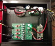
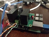
Since you asked, it motivated me to spend some more time with the x8 front end. I have it in a case now, along with an Amanero and 5v regulated power supply. Listening to it on test speakers now (still not confident enough to put it in front of a powerful amp and expensive speakers).
I did find one of the boards has a problem, didn't feel like debugging today. (The GND+NEG output pins are totally noisy, in either single-ended or balanced mode. Suggests I have another solder bridge somewhere on the "lower" four tda1387 chips.)
The board in the picture works, but I think one of the tda1387 chips isn't soldered correctly (or I have a bum chip, but most likely it's my bad soldering job). I have the output wired for single-ended mode (POS and NEG pins tied together), but accidentally configured the HC86 for balanced mode. This I believe should have resulted in no sound at all (i.e. the signals should have cancelled each other out). But I still got sound, although it was very faint. I fixed the HC86 jumper, and now there's a lot of gain (relatively speaking anyway). FWIW, I'm using software volume control, and have it turned almost all the way down.
In short, still feeling the pain of the initial sloppy soldering job. 🙄
Hopefully I'll have time tomorrow to finish the case work. I just need to drill out the real panel.
Attachments
Here's the BOM for the v1.0 board (i.e. what I originally posted in this thread, and what I've built up and am currently testing). The attached zip file has the BOM in several different formats - MS Excel, ODS, PDF and CSV.
You'll see one of my errors - the tda1387 pin5 (supply voltage) decoupling caps are inconsistently sized. Some are 805 size and some are 1206 size. Either way, they go on the bottom of the board.
I also included Mouser part numbers for reference. Obviously you don't need to pick the exact same parts, but I always like having an explicit reference. I put some basic notes in there too... e.g. if you're building this up strictly as a front-end (i.e. direct current-out, some external I/V), many of the parts can be omitted.
Let me know if you have any questions!
Attachments
Since you asked, it motivated me to spend some more time with the x8 front end.
Looks very neat! Are you planning to add an active I/V also at some point? I am hesitating to do more mods on my taobao 8x (like the CCS and filter) lest it stops making music.
I hope to, time permitting. That was the idea behind this design, to make it easy to try different I/V stages, or just go with a simple passive. The I/V I'm most interested to try is Abraxalito's.Looks very neat! Are you planning to add an active I/V also at some point? I am hesitating to do more mods on my taobao 8x (like the CCS and filter) lest it stops making music.
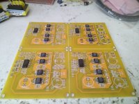
My gf's first PCB design has just come back from fabrication - its a quad chip version of Matt's board, 5*5cm, so we've panelized four to fit the 10*10 footprint that PCB vendors seem to offer their best prices on. Once its stuffed and proved working then anyone can build one - not that I'll be shipping out boards (as Matt's shown, that's not cost-effective), rather the data will be free to use on request. The cost of this first batch worked out to be around four boards for 1 USD.
One of these boards, together with the up-coming filter I/V board (about to enter layout any day now) will allow construction of a lingDAC.
One of these boards, together with the up-coming filter I/V board (about to enter layout any day now) will allow construction of a lingDAC.
Attachments
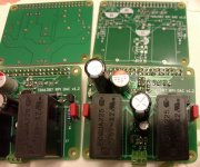
Thanks Matt - I haven't listened to lingDAC on speakers yet as I need an amp which is up to the job, haven't built it yet. Have been working lately on an amp to drive my 600ohm DT880s from this - the trafos for that are in the top-left of the DAC boards pic 🙂
One of these boards, together with the up-coming filter I/V board (about to enter layout any day now) will allow construction of a lingDAC.
I also can't wait to hear this DAC with your filter& I/V board.
I hope to, time permitting. That was the idea behind this design, to make it easy to try different I/V stages, or just go with a simple passive. The I/V I'm most interested to try is Abraxalito's.
Can the TDA1387 be soldered by hand with just patience, normal solder and a fine tip? It wasn't too bad adding caps on the chip pins.
And if going single-ended and 4 chip, would I be able to omit the logic inverter chip?
I must've soldered hundreds of TDA1387s down on 0.1" pitch perfboard. Soldering to the PCB was a doddle compared to that. Yes you'll need fine solder (I use 0.5mm) to avoid getting too much on the pads, which then leads to shorts.
You're right for single ended use there is no requirement to employ the HC86. If you omit it you'd need to wire across its pins in various places to get the I2S signal into the DAC chips.
You're right for single ended use there is no requirement to employ the HC86. If you omit it you'd need to wire across its pins in various places to get the I2S signal into the DAC chips.
Can the TDA1387 be soldered by hand with just patience, normal solder and a fine tip? It wasn't too bad adding caps on the chip pins.
What I've done when manually soldering is to first put some solder on the chip pads (i.e. pre-tin the board's IC pin pads). Then I hold the IC itself in place with precision tweezers, and just "brush" my soldering iron across the pins. I've found this to generally be pretty quick and easy, and actually looks good too!
The other method is the "stovetop reflow": first I put a skillet on our cooking range, and turn it up to medium heat (I have a cheap dedicated skillet just for this purpose). I put solder paste on all surface-mount pads on the PCB, and then drop all SMD components in their place. I then place the PCB on the now-hot skillet. I crank up the heat and watch for the solder paste to melt (very obvious, goes from a dull grey to a shiny silver). Once all the solder paste has melted, I kill the heat and remove the PCB from the skillet, and let it air cool. It's fun to watch the the surface tension of the melted (fluid) solder paste perfectly align the SMD components. This results in a very clean "made by robots" look.
I've heard about people using their cooking ovens to reflow as I've described. Not sure I want to off-gas my lead-based solder paste in the same oven that we cook family food in. But some day I plan to look for a cheap toaster-oven with temperature control in a thrift store that I can dedicate to this purpose.
Matt and Abraxalito, thanks for your encouragement and instructions, I am going to do it! I will order up the parts and PCBs once the Lingdac I/V is finalized.
Off-topic and perhaps too soon: do you think the Lingdac I/V stage would run well straight into a 10k potentiometer to a tpa3245evm board? The 8x DAC with the AD845 I/V sounds a bit anemic on this setup. If not, I'll start working on a buffer stage (i.e. Kuartlotron or DCB1) in the mean time.
Off-topic and perhaps too soon: do you think the Lingdac I/V stage would run well straight into a 10k potentiometer to a tpa3245evm board? The 8x DAC with the AD845 I/V sounds a bit anemic on this setup. If not, I'll start working on a buffer stage (i.e. Kuartlotron or DCB1) in the mean time.
The way I have the I/V stage of lingDAC configured now it doesn't have particularly low output impedance (its about 600ohms). So I would not recommend it straight into any classD amplifier. And definitely not via a pot into a classD amp as the pot will raise the output impedance even more (to 2k5 or so with 10k pot).
The TDA1387 lends itself to a volume control based on varying the pin7 voltage which I think will be better than using a pot. I am still considering the best way to tweak pin7 on my DAC. Incidentally I strongly recommend connecting a DAC to a classD amp via a transformer for best dynamics. I guess I need to design a trafo-output DAC especially for those who want to couple to a classD (that includes myself 🙂).
The TDA1387 lends itself to a volume control based on varying the pin7 voltage which I think will be better than using a pot. I am still considering the best way to tweak pin7 on my DAC. Incidentally I strongly recommend connecting a DAC to a classD amp via a transformer for best dynamics. I guess I need to design a trafo-output DAC especially for those who want to couple to a classD (that includes myself 🙂).
The way I have the I/V stage of lingDAC configured now it doesn't have particularly low output impedance (its about 600ohms). So I would not recommend it straight into any classD amplifier.
Can you elaborate on that?
Also, the opposite question: for the component that follows the lingDAC, what input characteristics are ideal?
There are a couple of aspects to consider here - first that many (not all) classD amps have rather a low input impedance - some as low as 3k. Putting that kind of load on the output of lingDAC is likely to make a small change to its frequency response. This is the lesser of the two issues.
The more important one is that classD amps generate a fair amount of noise (from their outputs) which can be picked up capacitively at the input - a high driving impedance here facilitates that pick-up. So to drive such amps I'd incorporate a buffer (emitter or source follower, biassed with CCS) to lower the output impedance by a factor of 10 or more. I already have a version of lingDAC with such a buffer which works fine - having a buffer means there's no longer any requirement for 4 paralleled DAC chips at the front end, even a single TDA1387 can be used.
The unbuffered lingDAC prefers to see a load of at least 20k.
Finally...
For the single-ended RPI Hat:
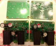
OK, third time's a charm (hopefully). First batch of these I used the wrong footprint for the tda1387 chip, so they were worthless.
On the second batch, I made some mistake exporting the Gerber files, so the boards came back without any ground plane. I suppose they are not technically worthless, but I didn't want to deal with it.
This batch corrects the above two mistakes. I soldered up a couple boards tonight. Testing will have to wait for another day.
I hand-soldered everything, my last couple attempts at the "stovetop reflow" ended up not going as well as I hoped. So I thought I'd keep things simple this time.
Let's hope they work!
For the single-ended RPI Hat:
OK, third time's a charm (hopefully). First batch of these I used the wrong footprint for the tda1387 chip, so they were worthless.
On the second batch, I made some mistake exporting the Gerber files, so the boards came back without any ground plane. I suppose they are not technically worthless, but I didn't want to deal with it.
This batch corrects the above two mistakes. I soldered up a couple boards tonight. Testing will have to wait for another day.
I hand-soldered everything, my last couple attempts at the "stovetop reflow" ended up not going as well as I hoped. So I thought I'd keep things simple this time.
Let's hope they work!
Attachments

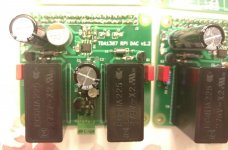
At least one board is working! I had a little time to give one of the completed boards a test. Worked without any issues. I didn't have any time for any kind of serious listing, but no obvious problems.
I have a pair of Overnight Sensations speakers I use as test speakers (the drivers are cheap in case I blow them up). As soon as I was confident this DAC won't kill speakers, I switched over to my Speedsters. I can say the DAC is at least resolving enough that the quality difference between the two different speakers was immediately obvious.
Once again I have a few extra boards, free to anyone who's willing to cover shipping. (I wonder if I could just drop one in an envelope and send it via first class mail, i.e. with just a stamp?)
Attachments
The way I have the I/V stage of lingDAC configured now it doesn't have particularly low output impedance (its about 600ohms). So I would not recommend it straight into any classD amplifier. And definitely not via a pot into a classD amp as the pot will raise the output impedance even more (to 2k5 or so with 10k pot).
The TDA1387 lends itself to a volume control based on varying the pin7 voltage which I think will be better than using a pot. I am still considering the best way to tweak pin7 on my DAC. Incidentally I strongly recommend connecting a DAC to a classD amp via a transformer for best dynamics. I guess I need to design a trafo-output DAC especially for those who want to couple to a classD (that includes myself 🙂).
Hi, do you happen to have a simple schematic or sketch on how to couple an audio transformer with a single ended DAC like this one? I would also like to use it in combination with a class D amp;
also, would this type of transformer be compatible? thanks
http://ro.farnell.com/vigortronix/vtx-101-007/transformer-audio-1-1-1-1/dp/1674305
- Home
- Source & Line
- Digital Line Level
- tda1387 dac pcb "front end"