I used the 3rd order filter in my DSD version partly because of my personal dogma about keeping things simple but primarily on cost grounds - the project was a bit of a leap of faith and not cheap. It sounds fine but now I have that positive experience I would like to explore alternative output arrangements including the fifth order filter, IIRC, that marcel spec'ed out.
Next question. In the LA article you mention up to 10mVrms of out-of-band noise in PWM8 mode. It looks like this is the noise level at the output of the dac after the 6th order filter and output transformer.
It was actually measured with filter, without transformer.
Have the frequencies of this remaining noise been measured or do you know the spectrum of frequencies and levels to target with the filter. I'm trying to establish a baseline for acceptible minimum performance of the filter based on the noise spectrum either remaining after the filter or to be targeted by the filter in general.
Obviously the original dac uses a sixth order filter and there are good reasons for that but the DSD only version ended up with 3rd order filter.
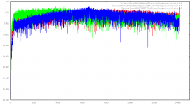
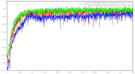
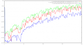
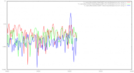
I can't measure that with the equipment I have at home, but I have simulated data for the shaped quantization noise spectra (without any reconstruction filtering), see the attachments. The frequency is in units of 27/28.224 kHz (so 14112 on the plot is actually 13.5 MHz) and the y scale is in arbitrary units that are proportional to voltage. Red is PWM4, green PWM8 and blue is chaos.
Looking at these plots, it seems that the chaotic mode has the best in-band noise floor, but that's because the second-order effects that actually determine the in-band noise floor are not included. In reality, PWM8 works best except regarding the out-of-band noise.
Like I wrote in the ThevalveDAC_PCB.pdf file included in the zip archive on the Linear Audio website, I expect that the Gaussian to 6 dB filters invented by DeVerl S. Humpherys give a much better suppression of out-of-band noise than my phase linear to 0.05 degrees filter. They will especially suppress the noise at a few hundred kilohertz better. Tables for these filters are included in Zverev's book.
Attachments
Last edited:
Thanks for taking that leap Ray.
I think the output stage including the filter will have quite an influence on the final sound of the dac and see lots of potential for experimenting in that area...hence my inquisitiveness. Have never built a dac before, only bought them, and have an excellent high-end R2R NOS dac here to compare. Am really looking forward to the build with the first partts arriving today.
I think the output stage including the filter will have quite an influence on the final sound of the dac and see lots of potential for experimenting in that area...hence my inquisitiveness. Have never built a dac before, only bought them, and have an excellent high-end R2R NOS dac here to compare. Am really looking forward to the build with the first partts arriving today.
It was actually measured with filter, without transformer.
So the performance should be a little better with the transformer attenuating/cutting off the UHF.
According to those graphs noise is spread throughout the frequency spectrum but the stuff in-band cannot be touched by the reconstruction filter. This is some incentive for a low cutoff frequency and higher order slope. But the ears will tell the story as to how much out of band noise is too much and experimentation is on the cards. Time to update the spreadsheet with more filter types and orders, plus be ready to run two or three filter pcb's so comparisons can be made. Sigh...
Thanks Marcel.
How are people handling the inputs? I was thinking of ordering a PCB to mount an optical port, BNC connector, and AES. Not sure how I want to implement USB yet.
Marcel, I got the parts to wind the inductors, but the insulating washers for the winding core were not included. I notice you don't mention them on the schematic. Are the insulating washers not needed?
I don't think they are needed, not even for the alternative circuits of post #1278 and definitively not for the original circuit with two DC blocking capacitors per channel. At least I didn't use insulating washers, only potcores, coil formers, base plates and "enamelled" wire, and everything works as intended.
Am yet to really look into how usb can be implemented. Both usb and hdmi inputs are needed here which may be an issue because both need i2s and I think only one of those ports are available.
One or two 74LVC157 multiplexer chips could solve that, although muting during switchover may complicate things a bit. You would have to first activate the mute, wait, switchover the multiplexers, deactive the mute.
Marcel, I remember reading about an i2s input being added to the capabilities of the original dac, but the search function here at diyaudio does not work with only three letters and I cannot see anything in the Linear Audio article nor a U.fl connector in the pcb bom and am yet to have any pcb's to look at. Could you please elaborate how to make the i2s connection? Am considering options like the IanCanada FifoPi or perhaps the Well Tempered offerings to enable USB/HDMI/Optical inputs for the original ValveDac as well as the Rpi for streaming.
Have a look here Downloads | Linear Audio and scroll down to "Design data package for Marcel van de Gevel's Valve DAC from Vol 13". Version 2.1 of the configuration file (the one programmed into the FPGA module that's on its way to Australia) uses the extension header as an I2S input.
Getting back to the question about how to connect a Raspberry Pi to the I2S input of the original valve DAC (with configuration file version 2.1): I don't see the point of fancy reclocking boards with ultralow jitter/phase noise oscillators when the DAC has an asynchronous sample rate converter with a slow sample-rate-ratio estimator, like the original valve DAC has. The jitter of the signals driving the DAC core will in any case be determined by the simple balanced TPTG oscillator built around an ECC81.
I would therefore just connect the Raspberry Pi's I2S outputs straight to the valve DAC. Assuming a Raspberry Pi model 3B running Volumio, you can simply connect it like this:
Pi's pin 35 (GPIO19) to DAC's lrcki2sin (P9 pin 11)
Pi's pin 40 (GPIO21) to DAC's datai2sin (P9 pin 5)
Pi's pin 12 (GPIO18) to DAC's bcki2sin (P9 pin 9)
Pi's pins 14, 34 and 39 (subset of its GND pins) to DAC's ground (P9 pins 2, 4, 6, 8, 10, 12, 14 and 16)
and indicate to Volumio that it is driving a generic I2S DAC. The DAC's mutei2sin (P9 pin 3) has to be grounded. The DAC's sel4192in (P9 pin 1) can either be grounded permanently when only the I2S input is used, or be connected to an extra contact of the source selection switch so it only gets grounded when the I2S input is selected. The other pins of P9 need not be connected to anything as long as you don't require the raw DSD interface or the deemphasis.
Connecting more than one I2S source requires some kind of multiplexer or switch to funnel it through the single I2S input.
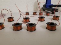
Wound all the inductors while I wait for other parts. I think my thumbs have arthritis now...
They look good! I hope your thumbs recover...
I Marcel
How many meters of wire does it take approximately to wind the inductors? I have a 0.6mm silver wire coated with Teflon, could I also use it?
How many meters of wire does it take approximately to wind the inductors? I have a 0.6mm silver wire coated with Teflon, could I also use it?
It takes a lot. Not even accounting for the added thickness each time you add a layer of wire around the former, you would need at least 20 meters for the default number of turns. The center of the coil former is about 12mm in diameter, so circumference ~38mm, 130 turns for a set of inductors = about 5 meters. There are 4 sets of inductors, so 20 meters without even accounting for wire thickness. Probably going to be more like 30-35 meters.
Last edited:
I have a 0.6mm silver wire coated with Teflon, could I also use it?
Definitely, if you have enough of it and if it fits on the coil formers. See SonnyMarrow's answer for the length.
...to enable USB/HDMI/Optical inputs for the original ValveDac as well as the Rpi for streaming.
Assuming the optical input is a TOSLINK-input, that can go via one of the four DIX4192 inputs, you just need to add an optical receiver module and a decoupling capacitor for its supply (few euros).
How many signals do you want to multiplex/switch to the I2S input? Three, one from a USB interface, one from an HDMI interface and one from a Raspberry Pi? Do you need the mute, de-emphasis and raw DSD functions for any of those?
My SACD player outputs digital via HDMI, coax spdif or optical. I've not listened to any of those outputs to figure which is best and I am not even sure the DSD layers will be put out over anything but HDMI...actually pretty sure they are not. This digital stuff is all new to me...my mind has been in the analog realm building amplifiers, preamps and phonostages...this is my first digital project and my knowledge is a little short in terms of protocols (and other areas as well!). Apparently the DSD "signal" is available to be extracted from HDMI video signal, and something like this little board can do it. Well it has I2S, coax and optical out, so turns out would even be suitable for routing via an optical input. Would like to find a more 'single use' solution because this board has lots of unnecessary things, but it would certainly do to initially test things.
Something like this optical receiver?
USB input: perhaps this one
I2S switching would be nice for the USB interface, the HDMI interface and streaming from the Rpi. No idea on mute, de-emphasis or raw DSD functions...I will have to research just what they are.
Something like this optical receiver?
USB input: perhaps this one
I2S switching would be nice for the USB interface, the HDMI interface and streaming from the Rpi. No idea on mute, de-emphasis or raw DSD functions...I will have to research just what they are.
See attached for two things: a comparison of the Linear Phase vs Gaussian 6th order filters for Fc = 82kHz, and the spreadsheet used to calculate the component values.
Note that this spreadsheet is useful only for current sources like the ValveDac and the DSDOnly variant...voltage source output stages need not apply. Both the 0.05deg Equiripple Linear Phase and Gaussian to 6dB filters are in the spreadsheet for all orders from 3rd to 6th and Marcels LC Interpolation method is used which means that filters can be calculated for different termination impedances (I am lowering the load impedance to improve the noise performance a little).
You enter your parameters in the yellow boxes and the green boxes give you the component values...it's that easy.
Standard source and termination impedances are 5600 and 375ohm differential respectively.
Anthony
Attachments

- Home
- Source & Line
- Digital Line Level
- Valve DAC from Linear Audio volume 13