A few months back me and a couple of friends decided to try our luck at a dual mono AK4490 design.
We chose to go with the AK4490 instead of the AK4497 because the latter was relatively difficult to find and frankly too expensive for a "learning project" of a DAC.
It was decided that it would be a modular design, with the DAC board separate from the analog stage and the receiver.
Since I was to do most of the design work on the DAC board I decided to try a number of "innovations".
I decided to use a programmable clock for a MCLK, since I wanted to experiment with the audible effect that different MCLKs would have (or not have). This would allow me to use the best possible MCLK for each supported sample rate. I chose to go with the well known Si570 part.
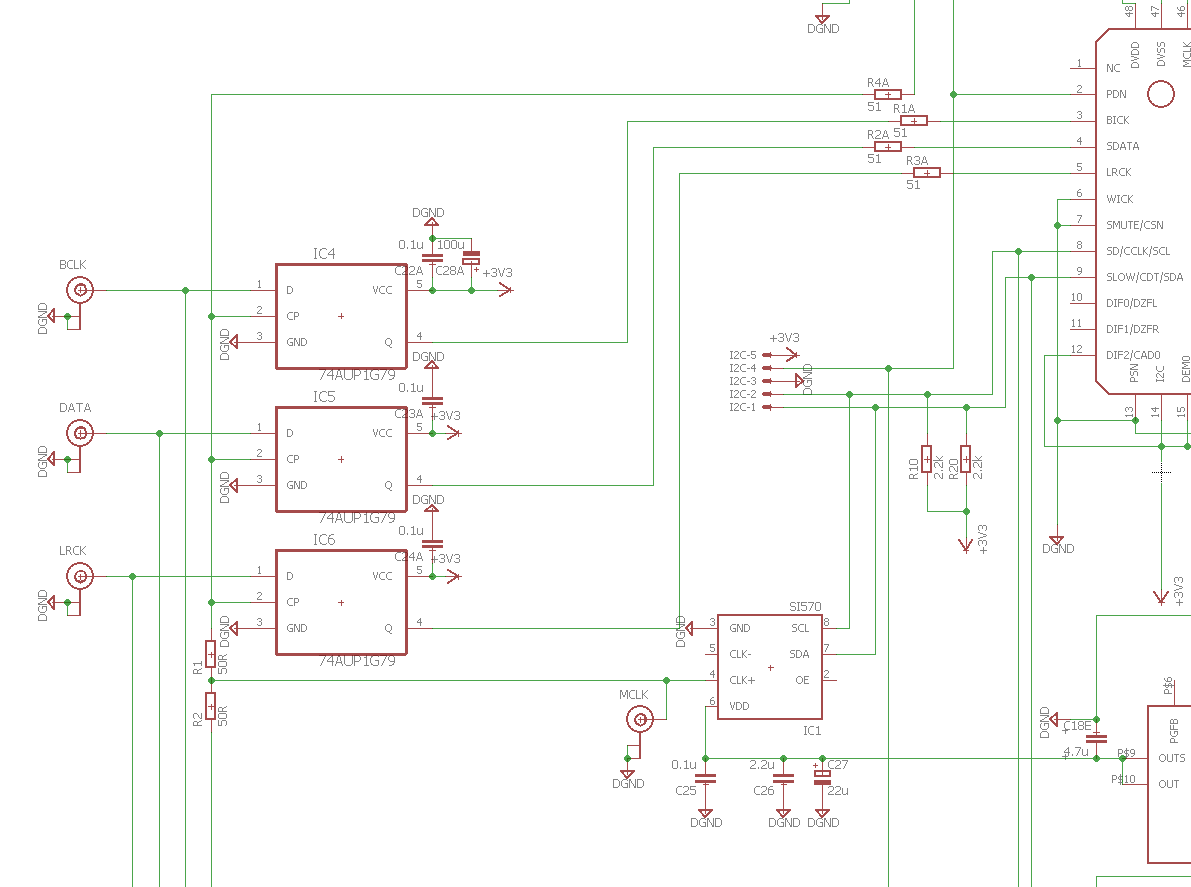
I also decided to do reclocking on all of the I2S signals a few millimeters before the signals would enter the DAC chips. I chose the 74AUP1G79 d-type flip-flops, as parts that were well regarded.
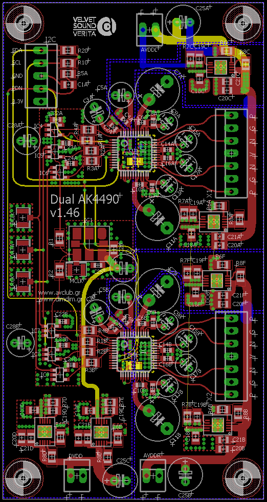
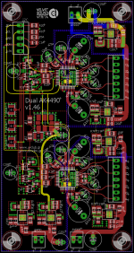
So I ended up with this 4-layer design:
I went with LT3042s as local regulators.
I would control it with an Arduino via I2C.
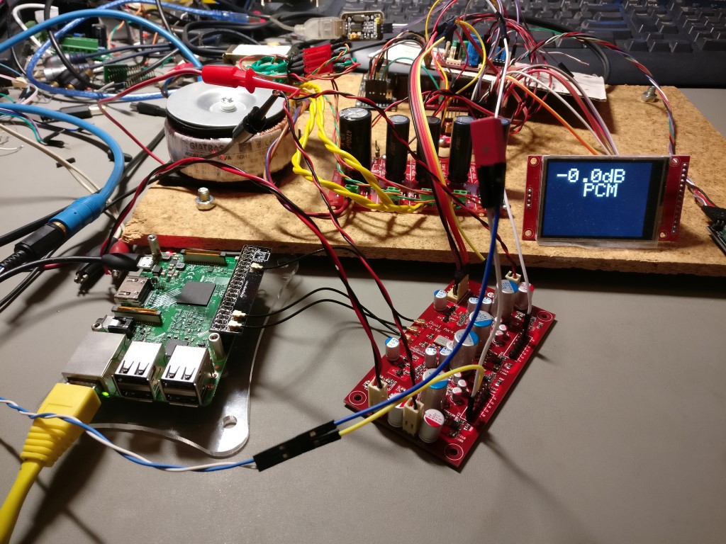
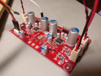
The boards were ordered and about a month later were delivered so I built a prototype:

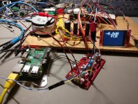
..and tested with an RPi as an I2S source:
Everything seemed to be working fine.
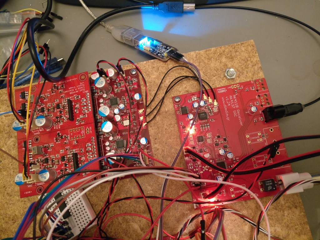
Meanwhile, I had also designed an AK4118 based s/pdif receiver with an on-board AK4137 SRC and a second selectable I2S source input (Arduino controlled of course..) and that had come along quite nicely. One of my friends had designed a class-A discreet analog stage for which I had designed a PCB and that too was working fine.
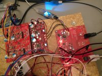
So we had come to the stage of the full system tests.
We then realized that there was a problem with the digital input of the DAC board. It seems that the signal "unlocks" every few seconds. This is not audible when playing music - that is why we hadn't noticed it until then. But when measuring by doing FFTs the noise floor would "jump up" every few seconds.
By doing several tests we concluded that our AK4490s don't like the reclocking of the I2S lines.
For the reclocking I have done this on my design:
but we are also getting the same results when bypassing my "questionable flip-flop design" and using Acko's well known reclocker.
The effect is the same no matter what we use as I2S source. The frequency of the "unlocks" depends on the sample frequency of the signal. Higher SRs result in more frequent "clicks". These "unlocks" are audible in relatively high frequency test tones (like for example at 10KHz) as "clicks". They are not audible during listening.
My good friend and accomplice Manolis (lemon) will post more info later today.
Has anyone else noticed this on their AK4490/4495/4497 DACs?
Any ideas why it may be happening?
Btw, as soon as we figure out what is going on with this issue, we will open up the project to anyone interested in building it. It already sounds pretty excellent as-is.
We chose to go with the AK4490 instead of the AK4497 because the latter was relatively difficult to find and frankly too expensive for a "learning project" of a DAC.
It was decided that it would be a modular design, with the DAC board separate from the analog stage and the receiver.
Since I was to do most of the design work on the DAC board I decided to try a number of "innovations".
I decided to use a programmable clock for a MCLK, since I wanted to experiment with the audible effect that different MCLKs would have (or not have). This would allow me to use the best possible MCLK for each supported sample rate. I chose to go with the well known Si570 part.
I also decided to do reclocking on all of the I2S signals a few millimeters before the signals would enter the DAC chips. I chose the 74AUP1G79 d-type flip-flops, as parts that were well regarded.
So I ended up with this 4-layer design:
I went with LT3042s as local regulators.
I would control it with an Arduino via I2C.
The boards were ordered and about a month later were delivered so I built a prototype:
..and tested with an RPi as an I2S source:
Everything seemed to be working fine.
Meanwhile, I had also designed an AK4118 based s/pdif receiver with an on-board AK4137 SRC and a second selectable I2S source input (Arduino controlled of course..) and that had come along quite nicely. One of my friends had designed a class-A discreet analog stage for which I had designed a PCB and that too was working fine.
So we had come to the stage of the full system tests.
We then realized that there was a problem with the digital input of the DAC board. It seems that the signal "unlocks" every few seconds. This is not audible when playing music - that is why we hadn't noticed it until then. But when measuring by doing FFTs the noise floor would "jump up" every few seconds.
By doing several tests we concluded that our AK4490s don't like the reclocking of the I2S lines.
For the reclocking I have done this on my design:
but we are also getting the same results when bypassing my "questionable flip-flop design" and using Acko's well known reclocker.
The effect is the same no matter what we use as I2S source. The frequency of the "unlocks" depends on the sample frequency of the signal. Higher SRs result in more frequent "clicks". These "unlocks" are audible in relatively high frequency test tones (like for example at 10KHz) as "clicks". They are not audible during listening.
My good friend and accomplice Manolis (lemon) will post more info later today.
Has anyone else noticed this on their AK4490/4495/4497 DACs?
Any ideas why it may be happening?
Btw, as soon as we figure out what is going on with this issue, we will open up the project to anyone interested in building it. It already sounds pretty excellent as-is.
Attachments
Dimitris described the problem very well, I couldn't to describe it better because my english is like the old man running!
I used the same AK4490 dual board, but with bypass the 74AUP1G79 d-type flip-flops due the Acko S03 reclocker that I have.
An Amanero board joined at the Acko S03 and the output of AckoS03 board going to u.fl of AK4490 board.
The output of the AK4490's analogue stage (I used a transformer output) captured by an EMU-0404 with ARTA FFT Analyser.
The same issue, the noise floor of signal jumps periodically (seems like signals unlocks for an instant) with no any particullary time. Every two seconds, every 6-10seconds, every 21 seconds, something like lotary! But, there is no any problem to any acoustic listening, no click, pop, scratch e.t.c.
This reclocker uses the Potato 74AUC1G74 chips d-type flip-flops.
If I remove the Acko reclocker and put the amanero alone, everything is OK!
With carefully, I examined the i2s signal by oscilloscope and compared the amanero output via reclocker output, but the signal was better on reclocker side, the data eye pattern was improved, the only strange point was a ghost signal with 20ns delay on reclocker bit clock ouput (look the next video).
The next video is the FFT issue with the noise floor pull-up every 10 seconds.
Last edited:
Have you try without programable mclk ? Can your board work in HW mode ?
Just making sure it hardware error not coding error
Just making sure it hardware error not coding error
Dimdim,
Does the unlock occur even on the lowest SR? Is there a debug register or pin from the DAC reporting something? Is the I2S clock jitter too high?
Does the unlock occur even on the lowest SR? Is there a debug register or pin from the DAC reporting something? Is the I2S clock jitter too high?
Have you try without programable mclk ? Can your board work in HW mode ?
Just making sure it hardware error not coding error
Manolis is running his board with MCLK coming from the Acko reclocker so no programmable clock. He is getting the same behaviour.
We haven't tried HW mode but the 4490 is a pretty "dumb" chip programming-wise. There is not much to mess up. I've tried running it in both Auto and Manual modes, it doesn't make a difference. What makes a difference is removing the reclocking stage - that fixes everything. So it's most likely a hardware problem.
But just to be on the safe side, I'll try to turn to HW mode a "practice" PCB that I have built. I'll have to check how feasible that might be, since it was designed to only run in SW mode.
Dimdim, lemon,
great work. Subscribed and following along.
Great project guys! Wish you luck on debugging
I'm tuned in
Thanks guys. 🙂
Dimdim,
Does the unlock occur even on the lowest SR? Is there a debug register or pin from the DAC reporting something? Is the I2S clock jitter too high?
The "unlock" (more like a "loss of sync"?) occurs regardless of SR. Its frequency of occurence depends on the SR - the higher the SR, the more frequent the "unlocks".
I considered that the MCLK might be "losing sync" with the rest of the signals so I tried varying the MCLK's frequency slightly (from a few Hz to a few hundred Hz). That made no change in the frequency of the "unlocks".
The 4490 offer no debugging registers.. they offer very little feedback as a matter of fact, not even a SR indication. I'd call them fairly "dumb", compared to their ESS competition.
The measured (audio) jitter is very low in all of our tests and the funny thing is that it improves further when the reclockers are in the chain, even though we are getting the "glitches"..
Did You try to invert the clock edge which is going to the reclock flip fllop?
Very probably You have a logic hazard situation, and You should introduce a delay (into the data path) But inverting the clock could be fortunate, and bring forward the moment of latching..
Problem is that with changing data rate You should continously control this situation..
Anyway, wanted to note that something similar happens also in other configurations, just released publicly, would not worry too much..
Ciao, George
Thanks for the encourage guys...
Joseph, we dont tried the input inverted pusle signal to the FIFO chips, but we'll tried...
Any suggestion that could to help us, is welcome.
Joseph, we dont tried the input inverted pusle signal to the FIFO chips, but we'll tried...
Any suggestion that could to help us, is welcome.
We can try that, inverting the MCLK and see if it changes anything.
A good logic analyzer would come in handy here.. It would be nice if we could capture the I2S signals both before and after the flip flops at the moment that the glitch occurs.
I did try to do that in fact, but couldn't manage to capture the exact moment of the glitch.
In my test my logic analyzer showed that the data stream remained bit perfect after the reclocking, though some of the samples were shifted a bit in time (due to the reclocking obviously..).
Anyone know of a good I2S test signal file? It would come in handy..
Not a digital audio expert here but would you be slaving the i2s sources with the si570 as the clock master? Sorry if I have neglected.
What is happening is that we are not using the MCLK from the I2S sources at all. We are just getting the BCLK, LRCK & DATA signals and reclocking them with our Si570's clock, which is also used as the AK4490's MCLK.
This tactic is followed by many reclocker projects.
This tactic is followed by many reclocker projects.
Then, is the si570 phase-locked onto anything? If it is let operate in free run, there will be occasions the D flip-flops get an input transition at its CK and D at the same moment causing output uncertainty, which translates to jitter equivalent to a clock cycle of the MCLK (the si570 puts out).
Hi Dimdim, great project.
Some though :
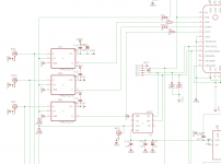
Have you tried to short R1 ? : assuming R4A is connected to MCK of both 4490 there are two RC network between MCLK input and the 2 4490. This may affect slope of MCLK on 4490.
Better implementation is maybe to have one 50R per input (on each D latch and on each 4497) rather than sharing the damping resistor. When sharing it, you sum the caps of each input.
Is it the same Si570 circuitry used when you try with and without the reclocker ? If not, you could consider that the issue is not the reclocker but the delivery of MCLK to the 4497. If I remember well AKM datasheet warns about relationship between MCLK signal and SNR.
Last think, UFL and coax are transmission lined, it may be useful to terminate them by 50 or 75R according your coax. Maybe they are, but it does not appear on the schematic fragment.
Inverting MCLK between the D Latch and the AK4497 is a simple thing to try too.
Some though :
Have you tried to short R1 ? : assuming R4A is connected to MCK of both 4490 there are two RC network between MCLK input and the 2 4490. This may affect slope of MCLK on 4490.
Better implementation is maybe to have one 50R per input (on each D latch and on each 4497) rather than sharing the damping resistor. When sharing it, you sum the caps of each input.
Is it the same Si570 circuitry used when you try with and without the reclocker ? If not, you could consider that the issue is not the reclocker but the delivery of MCLK to the 4497. If I remember well AKM datasheet warns about relationship between MCLK signal and SNR.
Last think, UFL and coax are transmission lined, it may be useful to terminate them by 50 or 75R according your coax. Maybe they are, but it does not appear on the schematic fragment.
Inverting MCLK between the D Latch and the AK4497 is a simple thing to try too.
Then, is the si570 phase-locked onto anything? If it is let operate in free run, there will be occasions the D flip-flops get an input transition at its CK and D at the same moment causing output uncertainty, which translates to jitter equivalent to a clock cycle of the MCLK (the si570 puts out).
The Si570 is not phase locked to anything, just its frequency is adjusted according to the incoming SR by the uC.
It makes sense that periodically things will get out of alignment, and that weird things will happen at that moment, but I didn't expect that to be audible, since this is not the first such implementation in our field.
Hi Dimdim, great project.
Some though :
Have you tried to short R1 ? : assuming R4A is connected to MCK of both 4490 there are two RC network between MCLK input and the 2 4490. This may affect slope of MCLK on 4490.
I can try that, even though I've checked the MCLK both at its source (Si570) and on the 4490's pin and they look pretty much identical.
The 4490s appear to be pretty tolerant of the MCLK. I've tried MCLKs starting at ~11MHz (the lowest specified) with no change. Manolis even tried a 3MHz signal that he had available, and the 4490 still produced sound (even though it had a lot of THD..). Even with a completely wrong MCLK, the chip works, even though the THD increases to over 3%.
Better implementation is maybe to have one 50R per input (on each D latch and on each 4497) rather than sharing the damping resistor. When sharing it, you sum the caps of each input.
You mean to put a 50R resistor before each flip-flop, plus keep the R4 resistors, right?
Information on proper termination of signals of this kind is kindda sketchy.. I've done a lot of reading and I still haven't got a proper grasp on it.
In case of the resistors before the flip-flops, shouldn't the termination be of "parallel" type? Via resistors to gnd? But since the source of the I2S signal will be "seeing" two resistors in parallel, it will be seeing half the resistance. But an even better way to go about it would be to buffer & split the signals properly. But that adds jitter. And so on, and so forth..
So I just left the signal as it was, improperly terminated. The pulses look just fine on the ol' scope, so it should be working OK.
Is it the same Si570 circuitry used when you try with and without the reclocker ? If not, you could consider that the issue is not the reclocker but the delivery of MCLK to the 4497. If I remember well AKM datasheet warns about relationship between MCLK signal and SNR.
We've tried both with the Si570 and without, with MCLK coming either from Acko's reclocker or directly from the Amanero with the same results. What I haven't tried (and I believe neither has Manolis) is Acko's reclocker on a single-4490 board with no reclocking. But I might be mistaken.. He'll let us know.
Last think, UFL and coax are transmission lined, it may be useful to terminate them by 50 or 75R according your coax. Maybe they are, but it does not appear on the schematic fragment.
Inverting MCLK between the D Latch and the AK4497 is a simple thing to try too.
See above, they are not, but that doesn't seem to impact the shape of the pulses.
I will try the inversion of the MCLK.
Hi Dimdim, great project.
Some though :
Have you tried to short R1 ? : assuming R4A is connected to MCK of both 4490 there are two RC network between MCLK input and the 2 4490. This may affect slope of MCLK on 4490.
Better implementation is maybe to have one 50R per input (on each D latch and on each 4497) rather than sharing the damping resistor. When sharing it, you sum the caps of each input...
Just I tried this.
I short the R1 & R2 with the 0R smd resistor and let only the R4A & R4B (they are the terminal resistors before input AK).
In other worlds, I have two resistors in the signal, one at the side of Acko's reclocker and the other at the end of signal before each AK.
Unfortunately, I have no any lucky with this!
My setup is different from Dimitris but with the same reclocking philosophy. The i2s signal runs from Acko's S03 reclocker, completely. I have no any local master clock on the AK board.
We are quite sure that this issue caused from reclocker side. Before, I have tried the Amenero (without any reclocking) to drive the AK board (dual mono) and everything was OK.
The Acko's S03 has two methods of master clock output. One mclk output relates with Amanero's mclk, this signal runs into the FF and each FF accepted the new clock pulse from the local recloking clocks (the signal is 22/24MHz), the other mclk outpute has no any relation with amanero's mclk because is driven from local reclocking clocks direct (the signal is 45/49MHz).
I have tried both of them, both had the same behavior on FFT.
Last edited:
What is happening is that we are not using the MCLK from the I2S sources at all. We are just getting the BCLK, LRCK & DATA signals and reclocking them with our Si570's clock, which is also used as the AK4490's MCLK.
This tactic is followed by many reclocker projects.
Dimdim,
Back from work I had a look the datasheet to confirm something I has in mind : according AKM datasheet (4495,90 & 97), phase of LRCK regarding MCLK doesn't matter BUT they have to be synchronous. That means you should reclock with the clock provided by your I2s source : AK4118 or AK4137, I dont know your setup. I believe you cant't use an arbitrary source even with close frequency, they will never be isochronous unless you sync with a gps...
But that seems to work without the reclocker... Maybe the reclocker influence, which resample the signals, highlight the little freq difference between the I2S source and the VCXO causing some bit loss when loosing a phase (H or L) from LRCK on a MCLK rising edge.
That may explain the relationship between the sampling frequency and the occurrence of the noise floor jump.
Easy way to confirm/infirm this hypothesis : remove the si570 and provide your DAC board with the MCLK out of your 4118.
Attachments
- Status
- Not open for further replies.
- Home
- Source & Line
- Digital Line Level
- Arduino controlled dual mono AK4490 DAC