24.576MHz seems to be good by the datasheet, if 192kHz should be considered too...
By designing the PSU, what is the current requirement (mA) for the Vref inputs? I can not find any information about that... Does it make sense to feed the 4 Vref inputs with more (e.g. 2) different regulators (shunts in my case)? I'am designing my DAC for an active system, so the L-R separation is an important point...
I don't know either the current consumption of the Vref inputs but it should be pretty low.
As for different regulators, in DIY world the more the better
 .
.From technical point of view maybe someone more skilled can give a better answer.
Hi,
not yet, I have buyed an oscilloscope 2 weeks ago and I'd like to finish my shunt regulators first. I made some experiments with my old PCM1794 too in terms of passive I/V conversion, so I am not bored...
But regarding to AK4458, I have some open questions yet:
- should I use an external 1,8V regulator or use rather the built-in chip version?
- should I make a pattern on the pcb for a master clock near the dac ic or place simply just a pin header?
- the optimal position for the small ceramic caps near the dac is on the top side direct by the ic. In my plan they are at the moment on the bottom side, separated from the ic pins by a via. It is not the best solution but more practical. Should I change this?
- I dont know what the current requirements of the Vref pins are...
- The filter section with opas is a separate panel, I must consider type of the ic-s (perhaps OPA1632 so-8, LM4562 dip-8, ...) and the layout according to this. For example: balanced, unbalanced, or both...
-....
If you have design ideas please let me know...
Last edited:
Hi,
not yet, I have buyed an oscilloscope 2 weeks ago and I'd like to finish my shunt regulators first. I made some experiments with my old PCM1794 too in terms of passive I/V conversion, so I am not bored...
But regarding to AK4458, I have some open questions yet:
- should I use an external 1,8V regulator or use rather the built-in chip version?
I'd use an external 1.8V reg.. I like to keep my DAC chips as cool as possible. Plus the external reg can be of higher performance than the internal one.
- should I make a pattern on the pcb for a master clock near the dac ic or place simply just a pin header?
For the MCLK I'd put the oscillator close to the DAC chip and use u.fl wires for the connection to the off-board DSP. You have already decided to also include a fan-out buffer, right?
- the optimal position for the small ceramic caps near the dac is on the top side direct by the ic. In my plan they are at the moment on the bottom side, separated from the ic pins by a via. It is not the best solution but more practical. Should I change this?
The theory says that you should, unless that messes up other more important routes, such as the I2S lines.
- I dont know what the current requirements of the Vref pins are...
The datasheet says max 41mA with 5V for the AVDD supply, as you probably saw yourself, so I'd budget at least that much for the Vref pins just to be on the safe side.
- The filter section with opas is a separate panel, I must consider type of the ic-s (perhaps OPA1632 so-8, LM4562 dip-8, ...) and the layout according to this. For example: balanced, unbalanced, or both...
-....
If you have design ideas please let me know...
Balanced vs. SE is a big decision.. SE is way easier, if you don't want/need balanced.
Thanks!!
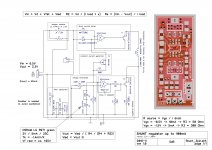
I set up my 3 pcs of 5V shunt regs to 50-60mA, for AVDD and Vref (2x), should be enough. Just a question: I read on your blog that you built another regs and throw away the Tridents. Why??
I'll make a pattern for the onboard oscillator (Crystek) + reg IC (in the case of needed), but the desired MiniDSP nanoSHARC can operate only as a master. That means I do not need an extra oscillator...
With a 2-layer board it is hard to meet all requirements of the "physics", so I think I leave the caps on the bottom side. I should maybe simulate what a via degrades on the signal quality...
When the Tridents were introduced a few years back they were very good, but time passes and the technology improves.. So now, Twisted Pear is selling their "Trident SRs" which are built around ultra low noise LDOs and I made my set of LT3042-based Trident replacements.
Subjectively, they sound clearly superior to the Tridents (especially the AVCC module).
Subjectively, they sound clearly superior to the Tridents (especially the AVCC module).
Do you mean it is a worth to use LT3042 instead of shunts? I want to try my own shunt (very similar to Tenlabs)... In what terms are they superior to Tridents?
(a comparison: USB DAC 2 - Hi-Resolution System)
(a comparison: USB DAC 2 - Hi-Resolution System)
I mentioned spot noise just because the Tent Labs shunt specifies it for their regulator.. It's just a way of "expressing" noise corresponding to a specified bandwidth.
Sure, all characteristics of the power supply matter, including output impedance in this case and PSRR.
Indeed, I have done listening tests with the LT3042 vs. the Trident units in my Buffalo and the LT was clearly better. More resolution, more natural sound, darker background.
But I have not done any comparative testing on AKM DACs (yet).
Thanks Dimdim!
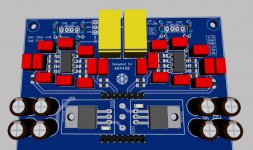
I think I'll design a small LT3042 panel, size und pin compatible with my shunts. This IC costs only about 5€. And then I can easy compare myself which is better...
(I will let manufacture with the DAC pcb-s together)
Do you have maybe a free design for that? Or are there some specialities?
I think I'll design a small LT3042 panel, size und pin compatible with my shunts. This IC costs only about 5€. And then I can easy compare myself which is better...
(I will let manufacture with the DAC pcb-s together)
Do you have maybe a free design for that? Or are there some specialities?
Slowly but surely...
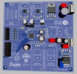
The filter pcb with only 4 channel and without copper pour yet (soon will be finished)...
I`ll order 10 pcs. from each pcb. Will somebody get from that?
The filter pcb with only 4 channel and without copper pour yet (soon will be finished)...
I`ll order 10 pcs. from each pcb. Will somebody get from that?
Attachments
Last edited:
- Home
- Source & Line
- Digital Line Level
- AK4458 multichannel DAC with I2S input