Many of the components of and near to the shunt regulators are getting too hot to touch. Only dare play it for a couple of albums as temperatures just seems to be increasing.
Concerned that the PSU caps are cooking and this will reduce their life span. Transformers are also getting very warm to touch. Probably heat soak from the resistors. Can't hold my finger on the resistors for very long.
Increased the resistors on digital circuit to 330 Ohm 1W. Other than possibly increasing the temperatures of the resistors it hasn't reduced the overall heat. The voltage drops with 220 Ohm across digital resistors was -9.24V and -9.27V. It is now increased to about -9.9V. So not enough difference to generate a lot more heat than original. The voltage drop on the digital section supply resistor was -5.48V, it's now -5.5V. Changed the digital circuit resistor from 41 Ohm to 56 Ohm 1W.
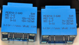
15V transformer is labeled 220V 15V/167mA 5VA. AC voltage is 246V.
(The OpAmp regs should be drawing about 42mA with NJM5534D. Supply current for one TDA1387T chip should be about 5.5mA)
Using it with the lid off at the moment. Have drilled a few holes in the bottom of case and PCB for better circulation. No noticeable change.
Mounted the new resistors with good clearance from PCB and each other where close.
Temporarily rested a 50mm 12V fan on top of case slots and that cooled things down a bit. However, the fan is too noisy and can be heard unless volume turned up very loud (and no quiet sections). May try running it at a lower voltage.
Could also try and find a 35 mm high TO-220 heatsinks in place of the 20 mm ones? Can't see if there is any heatsink compound on the existing ones. The heatsinks are varm but not hot.
Values of shunt regulator circuit:
C1 = 4700uF / 25V
R4 = 330R (was 220R, 150R originally)
R1 = 10KR
R2 = 2kR
R3 = 300R
C2 = 1000uF 25V
C3 = 1000uF 25V
C4 = 0.1uF 100V (now mounted under PCB)
Hi, I have also a Chinese USB DAC getting very hot by these shunt regulators.
I widened the hole in the PCB located in the middle of the heatsinks, for the +/- 15V supply. I also drilled 6mm holes in the bottom plate directly under the holes in the PCB. This way ventilation is much better and the heatsinks and the capacitors get much less hot.
STUPID design if you ask me.
Could someone post photos of 15v and 7,5v trafos? I'd like to know their nominal current. I bought DIY kit which did not include trafos and case. DIY kit seemed like a good idea for modding.
Could someone post photos of 15v and 7,5v trafos? I'd like to know their nominal current. I bought DIY kit which did not include trafos and case. DIY kit seemed like a good idea for modding.
Here are the 110v versions:
Attachments
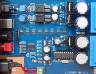
I've marked the caps to remove with a red X - the 2n2s are the blue ones. To the right are the supply decouplers (grey coloured).
Dear abraxalito,
Thank you for your research!
Do I remove both the 2n2ns and the supply decouplers? Do I need to bridge the locations?
Thank you!
Do I remove both the 2n2ns and the supply decouplers? Do I need to bridge the locations?
Remove the 2n2s entirely. No bridging necessary.
For the opamp supply decoupling, most people have removed the stock grey film caps, and replaced with as many caps as you can fit in there.
Take a look at post #186 on page 19 of this thread. I posted a pic that shows two of these DACs side-by-side, one completely stock (no mods), and the other with some mods. In particular, the modded one has the 2n2s removed and also the PSU decoupling caps replaced.
Lastly, if you haven't seen it already, take a look at the Wiki for this DAC.
Enjoy!
Hello DIY gurus.
I have this 1387 DAC and alongside playing music it makes a considerable amount of hissing noise be it connected to a notebook (I tried all the USB ports and a battery powered mode) , a droid phone (the lodest noises in this case) , anything. The return period is over. Any recommendations on how to fix it?
I have this 1387 DAC and alongside playing music it makes a considerable amount of hissing noise be it connected to a notebook (I tried all the USB ports and a battery powered mode) , a droid phone (the lodest noises in this case) , anything. The return period is over. Any recommendations on how to fix it?
Is it stock, or have you done mods?Hello DIY gurus.
I have this 1387 DAC and alongside playing music it makes a considerable amount of hissing noise be it connected to a notebook (I tried all the USB ports and a battery powered mode) , a droid phone (the lodest noises in this case) , anything. The return period is over. Any recommendations on how to fix it?
One of mine has the same behavior (hissing), but I always assumed it was a result of the extensive mods.
Often, hissing is a result of a ground loop. You have tried different sources, have you also tried different amps?
Also, it sounds like all your sources were USB based - can you try an optical (toslink) input? Optical guarantees you don't get any noise from the source.
One of the mods for this DAC deals specifically with output ground. You'll have to look at the wiki or dig through this thread - but there is a picture of the mod where a wire is run, on the bottom of the PCB, from RCA ground back to the mains earth. The idea is to give the RCAs a super low impedance ground. That might help you too.
What are you using for an amp?
1. Stock, no mods yet.Is it stock, or have you done mods?
One of mine has the same behavior (hissing), but I always assumed it was a result of the extensive mods.
Often, hissing is a result of a ground loop. You have tried different sources, have you also tried different amps?
Also, it sounds like all your sources were USB based - can you try an optical (toslink) input? Optical guarantees you don't get any noise from the source.
One of the mods for this DAC deals specifically with output ground. You'll have to look at the wiki or dig through this thread - but there is a picture of the mod where a wire is run, on the bottom of the PCB, from RCA ground back to the mains earth. The idea is to give the RCAs a super low impedance ground. That might help you too.
What are you using for an amp?
2. I tried an external amp when connected to notebook and the embedded amp when connected to a smartphone. Same result, even worse with smartphone.
3. Thought about the toslink, but the Ali specs claim it's a toslink/coax OUTput. I have a hidizs ap100 with a coax in, need to try though..
4. A wire mod, great, I'll try to implement.
The amp is Gustard H10.
In addition, standard windows7 drivers make it beep twice a minute. Ploytec drivers make the beeping go away.
1. Stock, no mods yet.
2. I tried an external amp when connected to notebook and the embedded amp when connected to a smartphone. Same result, even worse with smartphone.
3. Thought about the toslink, but the Ali specs claim it's a toslink/coax OUTput. I have a hidizs ap100 with a coax in, need to try though..
4. A wire mod, great, I'll try to implement.
The amp is Gustard H10.
In addition, standard windows7 drivers make it beep twice a minute. Ploytec drivers make the beeping go away.
The only output of the DAC is via the RCAs. Everything else is an input. IOW, the coax and optical are definitely inputs. I also never used mine with USB, actually, I did optical exclusively. So if you can easily test with optical, that would be a useful debugging step to see if we can track down the source of the hiss.
For reference, Malefoda's post #53 shows a pic of the output grounding re-route I mentioned in my previous post.
Before you fire up the soldering iron though: one thing I remember about this board, the mains grounding is kind of cheesy. If you slide the PCB out, you'll see there's an exposed trace along one side, that makes contact with the chassis itself. But the chassis is anodized, so I don't think this actually works. I believe the right way would be to have a short, fat wire going straight from ground to mains earth. So you could try just taking the PCB out of the case and seeing if improving the basic grounding would help at all (e.g. use alligator clips from that PCB trace to mains earth).
Just running the board out of the case alone could possibly solve the issue. The components are jammed in there pretty tightly, it's possible something is touching the case that shouldn't be.
Side note: I recently moved to a new house, and in preparing my previous house for sale, I noticed that some of my outlets, though they had three pins, didn't actually have the safety earth/ground actually connected to anything! I don't know how this passed the code inspection, but my only guess is that maybe it's not necessary if the outlet is on a GFCI? My point is, check that your outlet actually has a legit ground!
Tried some of the things you suggest. Connection w/o the case did not gain any profit. Connection via toslink - no sound at all, maybe the toslink input is broken. The board itself looks a bit different from Malefoda's pic.
An externally hosted image should be here but it was not working when we last tested it.
Oh, that board is indeed very different than the main subject of this thread. So what I said about RCAs being output-only, and everything else being input, is true only for the main subject of this thread. I am unfamiliar with your board!
Is there a pot (volume control) on your board? If you have a way of controlling volume in some other way (e.g. downstream component, such as integrated amp, or upstream component, e.g. digital/software volume control) - can you try turning the pot all the way up (i.e. full volume)? Pots themselves can sometimes introduce noise.
Another general idea: put a resistor across the signal and ground of each RCA output. Maybe try 100k ohm. (To be clear, you need two resistors, one for left-channel and one for right-channel.)
Is that powered via USB? Or does it take dedicated power input? Another thing to try, if it's powered via USB, is to use USB only for the signal, and provide power from a known good/clean 5V power supply. You can buy pre-made USB cables that do exactly this (they are literally "Y" shaped, where you provide the USB signal into one part of the Y, and 5V power into the other part of the Y). But you can hack up your own pretty easily by looking up the USB pinout reference.
Does that have a headphone output? If so, have you tried it to see if it also hisses?
Do you have a link to the sales listing?
That DAC I haven't seen before though I'm fairly sure its from the same vendor. There looks to be a headphone amp IC (the 8pin SOIC) and it has passive I/V rather than opamp. Note that the 620ohm resistors in the passive I/V stage are too high in value - they'll cause clipping about 3dB before digital full scale. Reduce them to 390ohm.
Powered via USB. The idea for a separate power source sounds great. Something like this, I believe? Wholesale USB 2.0 DUAL Power Y Shape to Mini Cable - 1MOh, that board is indeed very different than the main subject of this thread. So what I said about RCAs being output-only, and everything else being input, is true only for the main subject of this thread. I am unfamiliar with your board!
Is there a pot (volume control) on your board? If you have a way of controlling volume in some other way (e.g. downstream component, such as integrated amp, or upstream component, e.g. digital/software volume control) - can you try turning the pot all the way up (i.e. full volume)? Pots themselves can sometimes introduce noise.
Another general idea: put a resistor across the signal and ground of each RCA output. Maybe try 100k ohm. (To be clear, you need two resistors, one for left-channel and one for right-channel.)
Is that powered via USB? Or does it take dedicated power input? Another thing to try, if it's powered via USB, is to use USB only for the signal, and provide power from a known good/clean 5V power supply. You can buy pre-made USB cables that do exactly this (they are literally "Y" shaped, where you provide the USB signal into one part of the Y, and 5V power into the other part of the Y). But you can hack up your own pretty easily by looking up the USB pinout reference.
Does that have a headphone output? If so, have you tried it to see if it also hisses?
Do you have a link to the sales listing?
A headphone output is there. The noise is there when using it, too.
All in all, this DAC turns out to be a portable version of the stationary one being discussed here. The specs are in the first post: Hoved-fi - Vis emne - Lee Portable L1387 DAC/AMP The selling page
Dear abraxalito and Matt,
Thought I would move my questions into the TDA1387 thread.
So far I have:
1. Op-Amp Replacement with AD845
2. Removed 2n2 Opamp Feedback Capacitors
Trying to follow along to the TDA1387 mods, seems next is to increase Capacitance Across TDA1387 pin7.
Seems future mods include LC filter, passive IV and removing the opamps.
Thank you for the guidance.
- Mark
Hi Mark, sorry for the delayed reply. At any rate - I don't see an actual question in your post. Did you just want a suggestion on the next steps? Or clarification on a specific mod?
Removing Opamps
Hi matt_garman,
Thank you for getting back to me.
Have you modded your TDA1387 x8 to remove the opamps ? I believe the attached photos are the work of Malefoda. How does the sound change without the opamps ?
I believe without the opamps it becomes an all discrete DAC.
Thank you,
- Mark
P.S. So far I have:
1. Op-Amp Replacement with AD845
2. Removed 2n2 Opamp Feedback Capacitors
Hi Mark, sorry for the delayed reply. At any rate - I don't see an actual question in your post. Did you just want a suggestion on the next steps? Or clarification on a specific mod?
Hi matt_garman,
Thank you for getting back to me.
Have you modded your TDA1387 x8 to remove the opamps ? I believe the attached photos are the work of Malefoda. How does the sound change without the opamps ?
I believe without the opamps it becomes an all discrete DAC.
Thank you,
- Mark
P.S. So far I have:
1. Op-Amp Replacement with AD845
2. Removed 2n2 Opamp Feedback Capacitors
Attachments
Hi Mark,
No, I never modded this DAC to work without opamps. That's partially due to not having as much time as I'd like to work on these things, and also partially having some neurosis for neat and tidy work. I couldn't see any easy way to build the discrete circuit and keep things reasonably contained in the stock chassis. (There's a practical reason too: I have young kids running around, so it's not safe to leave a rat nest of live electrical stuff out where they can get to it.)
I could have moved the PCB into a bigger chassis, but it doesn't have any screw holes.
At any rate, that's a big part of why I designed the front end, so I could easily (and neatly) play with downstream filters, I/V stages, etc.
On your x8 DAC, I would try to add in the extra capacitance on pin7 of the tda1387 chips. At least in my case, I felt that was the one mod that had the most obvious impact, particularly in terms of bass.
Assuming you want to use the original chassis, you'll either have to get small diameter caps to put on the bottom of the board; or you can use bigger caps by soldering directly to the tda1387 chip pins (solder across pin7 (positive lead) and pin4 (ground)).
Does anyone think replacing the 12.000 mhz clock with a better one will be beneficial to the SQ?
Best,
Mark
Best,
Mark
Mark and Mark,
about the XO I am no expert but I don't think so, it's the source selector's IC under these 12MHz.
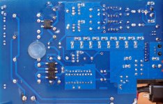
My DAC still runs opamps, AD845. The tiny boards on my pictured PCB are just tiny opamps adapter boards. But the DAC in the middle of the thread, USB powered, does run without opamp. Sound depends on next step's impedance. In my case bad sound.
Feed it with super clean SPDIF, the CS8416 is not the chip of the century.
about the XO I am no expert but I don't think so, it's the source selector's IC under these 12MHz.
My DAC still runs opamps, AD845. The tiny boards on my pictured PCB are just tiny opamps adapter boards. But the DAC in the middle of the thread, USB powered, does run without opamp. Sound depends on next step's impedance. In my case bad sound.
Feed it with super clean SPDIF, the CS8416 is not the chip of the century.
- Home
- Source & Line
- Digital Line Level
- TDA1387 x8 DAC: let's check its design, mod it -or not-, play music -or not! :(-