Folks:
Success! It's fascinating how very much improved this DAC now sounds as opposed to when it first arrived at my doorstep. My lovely wife, who supports my madness but is often indifferent to the quality of audio, remarked without any prompting that the DAC had originally sounded dull and lifeless and now sounds completely different ("musical, dynamic and lively" is what she actually said). I spent almost four hours listening last night and am looking forward to putting this DAC side-by-side with the Schitt Bifrost Uber in my main system for a closer comparison.
Thank you everyone, but most especially abraxalito, Matt and Malefoda!
Regards,
Scott
Attachments

This looks like a fun modding project. Problem is our 240-250v in Australia. Will I need to step down the voltage?
Not if you buy the version with 240V input 🙂
Oh good. But where is that option? Where did you get yours from?
Pretty sure I got mine here:
Won eight parallel TDA1387 L1387DAC 8X Hifi decoder TDA1541 masterpiece!
Note that the blue option is board only, and the black option is a complete unit. It doesn't include a USB module, but those are available from the same seller. You'll find links on the second page of this thread.
Won eight parallel TDA1387 L1387DAC 8X Hifi decoder TDA1541 masterpiece!
Note that the blue option is board only, and the black option is a complete unit. It doesn't include a USB module, but those are available from the same seller. You'll find links on the second page of this thread.
Another experiment
Just ordered one
What is the appropriate SMD package size for pin 7 pad? Looks like 0805. Plan to use 10uF 25V Ceramic multi-layer capacitors. Assume this should be good to replace the currently under dimensioned ones. Using very large electrolytic caps in this position seems an overkill. Must be a reason why ceramics are recommended by spec sheets for D/A chips?
Would LME49710 opamps be good for I/V conversion? (Already have a pair waiting to be used).
Although in this article the LT1028 measured particularly well for this application. https://www.by-rutgers.nl/IV-converter.html
First impressions
In stock form, string instruments sound a bit too metallic. General characteristic is that there is good separation between instruments with promising amount of detail without harshness.
Removing the 2n2 opamp feedback capacitors made sound appear unnatural almost like a bit of sustain with reverb added.
Replacing the NE5534s with LME49710s made recordings sound more natural. Acoustic nylon stringed guitars now sound right. Piano has good attack. Vocals are clear.
Have not noticed the NOS droop. Although, my tweeters are at least 2dB more sensitive than the mid range woofers. When I did a hearing test could not discern a 1dB difference.
Will try a few other mods like: CRC feeding opamps and polypropylene output decoupling caps. Maybe I can shoehorn 10uFs in there and change the ground resistors to 100k to avoid attenuating the LF (my pre-amp's pot is 20k).
Last edited:
In my experience, after different opamps, the next-best mod was adding capacitance to the tda1387 chip's pin7. At least I noticed a dramatic improvement in bass with that mod.
Overheating
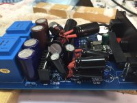
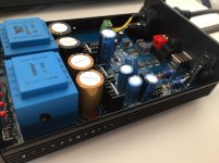
Does anybody have excessive heat generated by the DAC? Noticed case was quite warm from day one. Obviously the compact case has limited air flow:
The regulators/heatsinks are very hot, preceding caps are hot. The transformers are warm.
Operating with the lid off doesn't seem to make them much cooler.
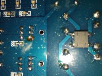
PCB coating around one of regulator legs is mis-coloured.
The transformers are labelled 220V.
Analogue PSU caps are 2 x 3300uF 25V 105deg. Mybe Panasonic [M]CE NHG?
Digital PSU caps are 2 x 4700 uF 16V 105deg. Labelled [M] CE FC. Maybe Panasonic FC?
Does anybody have excessive heat generated by the DAC? Noticed case was quite warm from day one. Obviously the compact case has limited air flow:
The regulators/heatsinks are very hot, preceding caps are hot. The transformers are warm.
Operating with the lid off doesn't seem to make them much cooler.
PCB coating around one of regulator legs is mis-coloured.
The transformers are labelled 220V.
Analogue PSU caps are 2 x 3300uF 25V 105deg. Mybe Panasonic [M]CE NHG?
Digital PSU caps are 2 x 4700 uF 16V 105deg. Labelled [M] CE FC. Maybe Panasonic FC?
Attachments
Last edited:
Mine pretty much never got fitted back into its case after the tsunami of mods began. But I also modded the hell out of the PSU from its stock form.
Sounds as if the shunts are running too much current into them, you might look into increasing the largish resistors which feed them, close to the transformers.
Sounds as if the shunts are running too much current into them, you might look into increasing the largish resistors which feed them, close to the transformers.
Power regulation
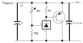
Assume this is the PSU shunt circuit with values:
C1 = 3300uF / 25V (too close to 24 V from transformer?)
R1 = 300R
R2 = 10kR
R3 = 2kR
C2 = 470uF 25V
Pass transistor pins 1. Base, 2. Collector, 3. Emitter (F C12 A940)
Voltage reference transistor pins: 1. Vref, 2. Anode, 3 Cathode (TL431)
Must be creating a lot of ripple current and/or drawing a lot of current if caps become very hot.
Attachments
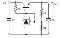
I'm not convinced that this is indeed the circuit. I seem to recall that its a transistor assisted shunt - the 2SA940 is a PNP whereas the transistor in your schematic is NPN. So the circuit is the one you see in figure 31 of the Texas Instruments datasheet for TL431.
Hi nige - I guess you're talking about pin7, it doesn't have the same function on TDA1387 as it does on TDA1543. Its a cap here because pin7 is a vref, not an iref.
oh that makes much more sense
think this is what threw me
what if we were to provide a reference voltage to pin 7?
was thinking voltage divider with resistor from battery supply
or supercapacitor
think this is what threw me
what if we were to provide a reference voltage to pin 7?
was thinking voltage divider with resistor from battery supply
or supercapacitor
Some mods and impressions
Have applied some mods. - In most cases adapted more modest capacitance increases. Changes so far:
1. Removed 2.2nF caps in feedback network of opamps.
2. Analogue PSU Nichicon UFW 4700uF bypassed with 0.1 uF (mylar). Resistors replaced with 220 Ohm. Gives deeper LF.
3. Shunt circuit analogue decoupling. Replaced the original 2 x 470uF and one pair of P bypass caps with 4 x Nichicon KA 1000uF x4. Left the inner pair of 104J100 bypass caps in place (one resoldered under PCB). Slightly better imaging / positioning.
4. Digital section TDA1387 supply: Replaced existing 470uF with a single Nichicon KA 3300uF. More well defined LF.
5. Replaced my previously installed LME49710 opamps with New Japan Radio NPN type NJM5534D's. These sound excellent - very neutral, open and instruments sound "true". Have not determined if a 22pF compensation cap from pin 8 to 5 is required?
A few hours of listening tests between changes of known material and another loved reference source. (No A-B comparison of a stock unit or prior to change version)
Next step: Change electrolytic output caps with Jantzen PP Cross-Cap 10uF plus a drain resistor change to around 100k (combination to ensure LF are not truncated).
Attachments

Heat problem persisting
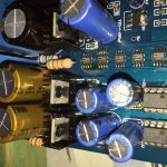
Many of the components of and near to the shunt regulators are getting too hot to touch. Only dare play it for a couple of albums as temperatures just seems to be increasing.
Concerned that the PSU caps are cooking and this will reduce their life span. Transformers are also getting very warm to touch. Probably heat soak from the resistors. Can't hold my finger on the resistors for very long.
Increased the resistors on digital circuit to 330 Ohm 1W. Other than possibly increasing the temperatures of the resistors it hasn't reduced the overall heat. The voltage drops with 220 Ohm across digital resistors was -9.24V and -9.27V. It is now increased to about -9.9V. So not enough difference to generate a lot more heat than original. The voltage drop on the digital section supply resistor was -5.48V, it's now -5.5V. Changed the digital circuit resistor from 41 Ohm to 56 Ohm 1W.
15V transformer is labeled 220V 15V/167mA 5VA. AC voltage is 246V.
(The OpAmp regs should be drawing about 42mA with NJM5534D. Supply current for one TDA1387T chip should be about 5.5mA)
Using it with the lid off at the moment. Have drilled a few holes in the bottom of case and PCB for better circulation. No noticeable change.
Mounted the new resistors with good clearance from PCB and each other where close.
Temporarily rested a 50mm 12V fan on top of case slots and that cooled things down a bit. However, the fan is too noisy and can be heard unless volume turned up very loud (and no quiet sections). May try running it at a lower voltage.
Could also try and find a 35 mm high TO-220 heatsinks in place of the 20 mm ones? Can't see if there is any heatsink compound on the existing ones. The heatsinks are varm but not hot.
Values of shunt regulator circuit:
C1 = 4700uF / 25V
R4 = 330R (was 220R, 150R originally)
R1 = 10KR
R2 = 2kR
R3 = 300R
C2 = 1000uF 25V
C3 = 1000uF 25V
C4 = 0.1uF 100V (now mounted under PCB)
Attachments
Last edited:
Increased the resistors on digital circuit to 330 Ohm 1W. Other than possibly increasing the temperatures of the resistors it hasn't reduced the overall heat. The voltage drops with 220 Ohm across digital resistors was -9.24V and -9.27V. It is now increased to about -9.9V.
With 220ohm as the original values your resistors were dissipating about 390mW. Well within a very comfortable margin for a 1W resistor. At 330ohm that's reduced to 300mW, so about 25% reduction. And you say that the resistor's temperature has possibly increased? But that would violate all known laws of physics unless you fitted lower wattage 330ohm Rs.
You have a maximum of 630mW in your shunt pass transistor which seems a bit on the low side, corresponding to 42mA totally. I can't from those figures work out a way anything much would get too hot to touch comfortably so perhaps something else is going on?
Hello!
I bought a mobile, a simpler version of the DAC. Playing it interesting.
Much depends on the quality of the power plug.
https://world.taobao.com/item/534981558156.htm?spm=a312a.7700714.0.0.fyIakR#detail
Did you tried to connect more power to your DAC?
In other projects, the AKM DAC is a very positive effect on the sound.
How is the power of your DAC? Shall describe what it eats stabilizers.
I plan this stabilizer powered DAC chips. It is very good to show themselves to other projects.
https://world.taobao.com/item/529758280774.htm?spm=a312a.7700714.0.0.lj7gFv#detail
And this stabilizer for operational amplifiers.
https://world.taobao.com/item/42793559763.htm?spm=a312a.7700714.0.0.CtfYgQ#detail
A few hours of listening tests between changes of known material and another loved reference source. (No A-B comparison of a stock unit or prior to change version)
Why no A-B? Wouldn't this point out the "real difference" between stock and modded? I mean, so much efforts and then no real comparison? 😕
- Home
- Source & Line
- Digital Line Level
- TDA1387 x8 DAC: let's check its design, mod it -or not-, play music -or not! :(-