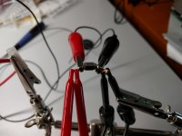
Success on the first try!
The time of wonders has not yet passed then
")
Capacitive encoder
How about a capacitive encoder? Even more reliable than optical.
AMT11 Series | Modular | Incremental | Encoders | CUI Inc
http://www.mouser.com/ProductDetail/CUI/AMT112S-V/?qs=Z/UIuWBNbssgaFjBBvUo1g==
$28 for a kit.
P.S.: I'm still looking for quality mechanical rotary encoder with smooth action. I've tested just few, but so far it seems that optical ones are in different league. The feel of optical encoder is really nice...
How about a capacitive encoder? Even more reliable than optical.
AMT11 Series | Modular | Incremental | Encoders | CUI Inc
http://www.mouser.com/ProductDetail/CUI/AMT112S-V/?qs=Z/UIuWBNbssgaFjBBvUo1g==
$28 for a kit.
Maintained list
Will you be maintaining the Mouser list? Does Farnell provide something similar?
I think these links could be put into the Github, and also perhaps a 'sticky' here. Would be quite nice references.
Will wonders ever cease?The time of wonders has not yet passed then
Will you be maintaining the Mouser list? Does Farnell provide something similar?
I think these links could be put into the Github, and also perhaps a 'sticky' here. Would be quite nice references.
I'm not sure what you mean by maintaing the mouser link?Will wonders ever cease?
Will you be maintaining the Mouser list? Does Farnell provide something similar?
I think these links could be put into the Github, and also perhaps a 'sticky' here. Would be quite nice references.
I have it in an e-mail, I think lol.
Anyhow, just an hour or so ago I actually got the widget control etc to work on my linux netbook. I want to be able to flash/update firmware without having to take the audio-widget board and whatever it's connected to and bring it to my bulky, watercooled win10 PC.
I got the parts not available at mouser from farnell, plus the resistors etc that I didn't get in the first order from mouser.
Hi,
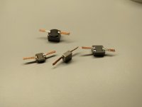
thx to my friend(thank you Honza) and his LabView skills I was able to do some crude C/W testing of the inductors. Test were rather rough - no climatic chamber/box, just a programmable power supply and constant power script in LabView. The winner is 7443340330(not on pictures), with cca 7.25C/W. The original part has C/W roughly twice as big. I have the new part soldered on one of blue boards and ready for some more testing
Layout is almost done, I'm going trough DRC checks and pondering about some footprint updates. Also two variants of rotary encoders are on the way - one from bourns, one from Alps.
Question for you guys (and gals.) ), do you like dents for volume control?
Take care,
Pitrsek
Attachments
Hi,
Question for you guys (and gals.) ), do you like dents for volume control?
Take care,
Pitrsek
Pitrsek -
No more 'dents,' Please - I'm already dense enough....
On the subject of 'detents,' I find them useful for variable resistors that control logarithmic functions (like some mixers have 1/10 dB detents, that let you quickly reset levels in between 1/2 dB markings. In all cases, they're useful where the circuit values are controlled in a predictable, step-wise fashion - so you want to hit a known increment quickly and repeatedly.
Indented controls seem less useful to me on linear, analog, or continuously variable circuits where whatever value they might have in repeatability is nullified when the setting you need lies right between the "!@#$%^&*" detents.
For example - if you're using a rotary encoder to switch a resistor network which gives highly repeatable outputs - then detents (with a blessed numeric readout of how many 'clicks' have been taken - NEVER trust the alleged humans in your process...) make good sense.
OTOH - if you're using a linear or audio-taper potentiometer to set an opamp's bias or to establish channel tracking, then detents merely show your profound contempt for the device's users, since a simple pot with an accurate and readable metering circuit is a much better solution when used with even a slight degree of facility.
Now, this is just one idiot's opinion - I'm sure that there are folks here with diametrically opposed opinions, based on their own experiences - and I certain that a statistically significant number of them may also be correct.
Cheers (ducking...)
Jim
Hello Jim,
thank you for the correction and your opinion!
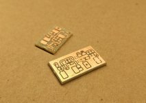
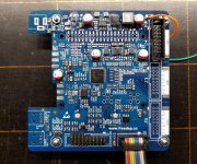
With B2 revision, there was no provision for powering down the expansion boards(ADC/DAC etc.), which is pity. For B3 revision I've designed simple high side switch. Before I close the pcb design, I just wanted to test the switch, so I lets have some test-boards. Second board is new and better power sequencing - resetting diodes and some minor tweaks. Again, just testing before using it in the the new revision.
Also we will have a AMA on 13.06. So if you feel like, please stop by!
thank you for the correction and your opinion!
With B2 revision, there was no provision for powering down the expansion boards(ADC/DAC etc.), which is pity. For B3 revision I've designed simple high side switch. Before I close the pcb design, I just wanted to test the switch, so I lets have some test-boards. Second board is new and better power sequencing - resetting diodes and some minor tweaks. Again, just testing before using it in the the new revision.
Also we will have a AMA on 13.06. So if you feel like, please stop by!
Attachments
Hello,
Wonderful project !!! I love it. Thanks a lot for this great project. I am considering building one or 2 in few month for my "audiophile" audio and home cinema setup, as an active crossover filter and delay for time alignment of the speakers.
I am considering the following inputs:
- R+L+Center+Sub for home cinema
- phono for high end audio
- Raspberry Pi 3
- SPDIF input
I need the following outputs
- 3 outputs for left channel (Bass, Med Treble)
- 3 outputs for the right channel
- 2 outputs for the center channel (Bass, Treble)
- 1 output for the Sub (may be an SPDIF output if needed)
I think your PiDSP will fit my needs.
After reading the B2 schematic you provided, I have few questions/suggestions...
For the questions:
- Does the I2S RPi output support TDM multicanal audio (5.1, 7.1) ?
- The I2C connected to the ADC/DAC connectors is the one coming from the DSP. Does Sigma Sudio provide the support to control the DAC via I2C ? Can we also use this I2C to control an analog potentiometer located after the DAC ?
- What is the difference between X1 and X ? The frequency ?
- What is the purpose f the SMA connectors ?
- Is it compatible with the Rapsberry Pi 3 ?
For the suggestions:
- Would it be possible to add an additional I2S connector (like DIO0, DIO1, DIO2) for the SDATA_OUT3 and SDATA_IN3 currently connected to the Raspberry: This would increase versatility when using in standalone mode (no Raspberry), and make it easier to connect 8 output audio channels (like I am trying to do)...
- What do you think about adding spare connectors on both I2C bus for future extensions ?
- And maybe connectors to connect Digital microphones ?
Thanks again for this project and for your inputs.
Best regards.
Hello nbremond
As for suggestions:
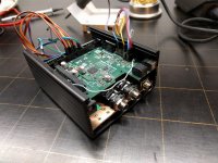
I've tested the high side switch module and improved startup timing, both works well. I'll finish populating the board, so I have one more functional RPI.
- Sorry, the RPi does not support TDM output. If you want to use 5.1/7.1 with Rpi, you need usb-I2S bridge. To my knowledge, Beaglebone does support 5.1, some other SOCo as well, but unfortunately that functionality is not usually implemented.
- Yes, you should be able to DACs/ADC I2C volume control from sigma studio. I write should, because I did not test it.
- Multiple oscillators are provided as per request. You can play with multiple FS without the need for ASRC. It was easy to implement, and did not take too much board estate.
- SMA connectors are used for impedance and noise measurements on power supplies
- Yes, it is. *** well with other SBC that share form factor and pin-out of RPi2
As for suggestions:
- Sorry, connectors are finalized. You can use jumper wire and connect RPI header directly. Or make a simple adapter board.
- I2C from DSP is provided on three FreeDSP connectors, I2C from RPI is provided on front panel connector, programming connector and RPI connector.
Which I2C did you have in mind? - You can use any GPIO for digital microphone. There are 4 GPIO routed to front panel connector
I've tested the high side switch module and improved startup timing, both works well. I'll finish populating the board, so I have one more functional RPI.
Attachments
I've been following your project for a while. Very Nice! I'm definitely interested to get one when it's ready.
Not sure what compatible DAC boards might be available now (are there any?), but I'm planning to design one around the AK4454/6/8. Haven't decided how many channels, though I only really need 4. Looking at using AD8675 so far, but haven't really done a good job looking at noise numbers yet.
Cheers!
Not sure what compatible DAC boards might be available now (are there any?), but I'm planning to design one around the AK4454/6/8. Haven't decided how many channels, though I only really need 4. Looking at using AD8675 so far, but haven't really done a good job looking at noise numbers yet.
Cheers!
Hello,
This is a nice project. I am interested in using the PiDSP with a PiZero to create a USB Audio Slave Device with a DSP Mixer. I have a few questions about this project.
This project refers to the creative commons non-commercial license, whereas the Classic FreeDSP is a Creative Commons Attribution Share-Alike 4.0 license. The "Non commercial" license seems to be more limiting. So can this board be embedded inside a product that would be sold?
The other is regarding performance. This project uses the ADAU1452 but I noticed that the ADAU1467 is referenced in the datasheet as "pin and register compatible with the ADAU1450/ADAU1451/ADAU1452 SigmaDSP processors.". So can this project be upgraded?
I hope to have the opportunity to purchase one soon. Thanks!
From a quick look at the data sheets: the ADAU1452 is a 72 pin chip (10 X 10 mm package) while the ADAU1467 is a 88 pin chip (12 X 12 mm package). So an upgrade would require a different PCB. It appears the ADAU1467 has more program and data memory, but processes the same 6144 steps per sample. So no increase in the number of FIR traps. YMMV.
Hi,
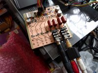
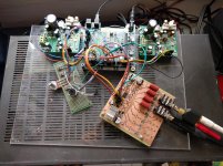
sorry all for a silent period. I was working on a budget(AK4440) 8ch DAC to go with the PiDSP. I had prototype up and running, even with I2C register setup. And was about to finish final board design, when I discovered that AKM decided to EOL this chip.... was in a bad mood for a while.
Anyway, I'm testing the blue board with all the changes.
I'm sorry that updates are few and long between, the thing is that the project has been in development for so long that my drive is not what used to be + other projects and life in general
@shuksan: Before the failed AK4440 DAC I've worked on DAC with AK4458 .Decided to do AK4440 instead - easier and cheaper. I'd be happy to have a chat about the DAC if you'd like.
@JayShoe: Yes, PiDSP is released under noncommercial licence. If you'd like to use it commercially, I'd be more than happy to have a chat about it(I could provide you with samples as well.).
About ADAU1467 - just opened the datasheet, depending on the pinout, switch might be relatively easy. The question is, is it worth it?
+2 aux ADC, +12GPIO, double the memory. I have nowhere to route the aux ADC and GPIO.... Maybe there is more to it, I just glanced trough.
Merry Xmas to you all
sorry all for a silent period. I was working on a budget(AK4440) 8ch DAC to go with the PiDSP. I had prototype up and running, even with I2C register setup
. And was about to finish final board design, when I discovered that AKM decided to EOL this chip.... was in a bad mood for a while. Anyway, I'm testing the blue board with all the changes.
I'm sorry that updates are few and long between, the thing is that the project has been in development for so long that my drive is not what used to be + other projects and life in general
@shuksan: Before the failed AK4440 DAC I've worked on DAC with AK4458 .Decided to do AK4440 instead - easier and cheaper. I'd be happy to have a chat about the DAC if you'd like.
@JayShoe: Yes, PiDSP is released under noncommercial licence. If you'd like to use it commercially, I'd be more than happy to have a chat about it(I could provide you with samples as well.).
About ADAU1467 - just opened the datasheet, depending on the pinout, switch might be relatively easy. The question is, is it worth it?
+2 aux ADC, +12GPIO, double the memory. I have nowhere to route the aux ADC and GPIO.... Maybe there is more to it, I just glanced trough.
Merry Xmas to you all
Attachments
I was working on a budget(AK4440) 8ch DAC to go with the PiDSP. [...] when I discovered that AKM decided to EOL this chip.... was in a bad mood for a while.
I'd be happy to have a chat about the DAC if you'd like
When I look at the available options for the FreeDSP expansion boards I think there is room for some "budget" IO board for starters and tinkerers. Expcecially for the PiDSP because it doesn't have any IO's besides the SPIDF ports. I'd be building something to become "in stock" and can be purchased pre-built and ready to go so users can get involved in FreeDSP easier. For me personally, I purchased a FreeDSP Classic but never purchased the parts or soldered it together yet.
I want to make an expansion board for FreeDSP using TLV320AIC3104 (or possibly 3106, because it has 4 i2C addresses. The 3104 would require an I2C multiplexor). What's nice about these codecs is that if wired right to a Header connector, the IO can be very flexible. (RCA, XLR, 1/4", 3.5mm, etc). Each single channel input and output would be a 3 pin header (+, -, GND). For a stereo single ended IO the dongles would lead to two headers, connecting only to the +/GND pins. They have enough power to run headphones, but can also do differential line outputs or single ended outputs as well. So it becomes a "switchboard" of such. But what I find intriguing about them the most is that they are budget. The sound quality is "good enough" and "much better than a PC sound out", but it's not audiophile and therefore it's not out of reach for basic uses. They can be mass produced at reasonable costs as the chips are around $1.70 - 1.95 per 1ku.
The plan is to have 4 of these chips on one board. The result is a 8x8 IO board with all IO's being switchable between balanced, or single ended. Plus the inputs have up to 59db of gain! It would use one FreeDSP header, and would use TDM on the Serial data in/out coming from the ADAU1452. Maybe my plan is something that you find interest in. I'd be very happy to contribute to the FreeDSP project with my custom IO Board if the FreeDSP team and contributors would be interested in the help and I can get the team on my side for the project. It might solve your goal to have an 8 DAC, with the bonus of also getting 8 ADC channels as well. I believe this would be a great starter board for most projects. Very flexible.
If we find some interest I can start a new thread and start posting my project details.
About ADAU1467 - just opened the datasheet, depending on the pinout, switch might be relatively easy. The question is, is it worth it?
Actually, it is probably not worth it. I read about it from another project and thought it might have advantages. It doesn't appear the advantages would be helpful.
Jan,
A question I have about your project is how the pi fits in. I am interested in control the DSP parameters "emulating sigma studio" so I can control it via the pi. I want to extend that control over usb to my PC.
The pi won't run sigmastudio. What if we used a pi zero and made a USB "sigmastudio to raspberry i2c bridge". Something that would accept commands from the PC. From within sigmastudio or from our own open source windows code.
This document outlines how to control the DSP using i2c and the methods for converting this control code to the mcu of choice. If our uC is the pi, I'm thinking I can turn the pi into a USB otg device. Then the pi zero will convert the USB to i2c to control the piDSP. I hope this makes sense. What did you have in mind when you first came up with the pi idea? How does my idea fit in?
How do I create the microcontroller code to int... | EngineerZone
Last edited:
- Home
- Source & Line
- Digital Line Level
- freeDSP V2.0 (ADAU1452) developement thread