I start this thread to investigate the opportunity for a diyer to build a real low jitter oscillator.
The great issue for a diyer is that typically he doesn't own the suitable gear to test the performance of an oscillator, so the results are uncertain.
The equipement to test the phase noise of an oscillator starts from some tens thousands dollars, and a diyer can't afford them.
The true guru in this matter, that you probably know as Jocko Homo, has demonstrated that one could build a low phase noise oscillator taking a crystal from the shelf with a simple pico gate. He did reach -122 dBC@10Hz from the carrier for a 11.2896 MHz oscillator, that's an impressive result.
But he did a strong selection of the crystal using a phase noise measurement system that costs 30,000 USD or more.
Moreover the crystals he had used, around 0.5 USD each from Mouser or Digi-Key, are no longer manufactured, and the supplier don't have anymore in stock. They were the cylinder crystal CSA309 from Citizen.
He also tested the HC49 type, but seems it's not perform like the above type.
You have to consider also that after the selection, only a few crystals can reach similar performance when placed in the oscillator, usually not more than 5%.
The other crystals were throw out, so the cost increases.
That's the reason I believe the goal is to start from a very good crystal, with high standard and repeatable features.
I will experiment with 3 kind of oscillator circuit to implement the above crystal: the Clapp crystal oscillator, the Butler two emitters, and the Driscoll.
The first oscillator is almost ready, with its own PCB, then I'll investigate the other two.
In the second and third circuits, the crystal see a very low impedance, and this usually guarantees a very high loaded Q.
When all the circuits will be ready, I can access a university lab to test them with an Agilent phase noise measurement system.
TWTMC project. For Schematics, BOM, PCB and Assembly guide see post #1506
The Well Tempered Master Clock - Building a low phase noise/jitter crystal oscillator
Group buy thread for this project is located at
The Well Tempered Master Clock - Group buy - diyAudio
New oscillators, frequency doublers and sine to square converters from post #3008
The Well Tempered Master Clock - Building a low phase noise/jitter crystal oscillator
Semi-finished boards BOMs update at post #3482
The Well Tempered Master Clock - Building a low phase noise/jitter crystal oscillator
User manuals
The Well Tempered Master Clock - Building a low phase noise/jitter crystal oscillator
Last edited:
The crystal
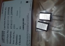
Since a very good crystal is the goal of this project, I got a custom device from the canadian Laptech Inc.
The most important features for a very good crystal are: cold welded package, very low ESR and very high Q, but overall its surfaces have to be strongly polished.
If the surfaces are not polished with the maximum care, the crystal shows some kind of perturbance that decreases its performance in phase noise close to the carrier.
The selected crystal is an HC/49U cold welded polished AT crystal.
These are the typical characteristics for a 11.2896 MHz crystal:
Mode: fundamental
ESR: less than 10 ohm
Motional capacitance: less than 12 fF
Q: better than 150 k
But features aside, the most important feature of the above crystal is that its features are standardized and repeatable.
The crystal is individually polished and tested from the manufacturer, that throw out the devices that not performs as specified.
When I got the first batch of 5 crystals, they were accompanied with a list where each crystal is tested individually. This list contains 12 tested crystals, but 5 only of them passed the selection.
Attachments
You can make PN measurements without needting tens of thousands of dollars of kit you know.
Look up the quadrature mixing method of phase noise measurement for example, Martein Baker PA3AKE goes into some details on using a relatively low cost spectrum analyser to measure close in PN by this method, personally I would build two identical clocks and just subtract 3dB from the measured output rather then trying to source a state of the art reference source.
Wenzel associates have some stuff in their library.
Low-Cost Phase Noise Measurement | Wenzel Associates, Inc..
How are you planning to do the limiting? Keeping the gain stage operating in its linear region is important to avoiding the conversion of AM noise to PM.
Have a look at some of the stuff folks like Driscoll have been doing for sources intended to be multiplied up into the GHz bands, there is some interesting work there, for all that series mode seems to be preferred in those (overtone) designs.
Regards, Dan.
Have a look at some of the stuff folks like Driscoll have been doing for sources intended to be multiplied up into the GHz bands, there is some interesting work there, for all that series mode seems to be preferred in those (overtone) designs.
Indeed I'm planning to use a 3rd overtone crystal for the Driscoll oscillator.
I got also some pieces of 3rd overtone crystals from Laptech.
These are the specs:
Frequency: 33.8688 MHz
Mode: 3rd overtone
ESR: less than 15 ohm
Motional capacitance: 1.35 fF
Q: better than 260 k
Andrea
The Clapp crystal oscillator
The first circuit I have built is the Clapp oscillator, a variant of the Colpitts.
The circuit was designed by a smart dutch guy, using only a few components.
The oscillator include one jfet as the active device, and a few capacitors and resistors.
Then a simple '04 inverter was used to square the sine waveform coming from the oscillator.
The circuit is intended for use with fundamental mode crystal, from 5 MHz to 25 MHz.
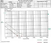
This oscillator was measured with a R&S FSUP system.
As you can see in the attached plot the performance is impressive:
-132 dBc at 10 Hz from the carrier and -101 dBc at 1 Hz
RMS jitter below 1 ps (0.4060)
One of the best AT crystal oscillator I have ever seen, not far from an state of the art OCXO.
Note that the oscillator performs much better using a 74HC04 for the squarer, rather than using a comparator such as the LT1016.
The crystal used comes from the german QT Quarztechnik GmbH.
It's a HC-49U resistance welded package, 15 ohm ESR, laser engraving strongly polished crystal. Very similar to the Laptech, that on the paper should be a little better, since it show lower ESR and comes in cold welded package.
The dutch guy measured also the oscillator with Laptech crystal (I sent him 1 piece) with his DC receiver. The DC receiver cannot measure the phase noise very close to the carrier. The results was:
at 200 Hz the noise is at the bottom of the DC-receiver: -157 dBc/Hz@200 Hz
at 50 Hz the noise is -155dBc/Hz@50Hz.
He said about the Laptech crystal "...one of the best Xtals I measured before! Moreover its microphonics is very low which makes it very suitable for a transport in the same room as the loudspeakers"
Next step: the circuit diagram.
The first circuit I have built is the Clapp oscillator, a variant of the Colpitts.
The circuit was designed by a smart dutch guy, using only a few components.
The oscillator include one jfet as the active device, and a few capacitors and resistors.
Then a simple '04 inverter was used to square the sine waveform coming from the oscillator.
The circuit is intended for use with fundamental mode crystal, from 5 MHz to 25 MHz.
This oscillator was measured with a R&S FSUP system.
As you can see in the attached plot the performance is impressive:
-132 dBc at 10 Hz from the carrier and -101 dBc at 1 Hz
RMS jitter below 1 ps (0.4060)
One of the best AT crystal oscillator I have ever seen, not far from an state of the art OCXO.
Note that the oscillator performs much better using a 74HC04 for the squarer, rather than using a comparator such as the LT1016.
The crystal used comes from the german QT Quarztechnik GmbH.
It's a HC-49U resistance welded package, 15 ohm ESR, laser engraving strongly polished crystal. Very similar to the Laptech, that on the paper should be a little better, since it show lower ESR and comes in cold welded package.
The dutch guy measured also the oscillator with Laptech crystal (I sent him 1 piece) with his DC receiver. The DC receiver cannot measure the phase noise very close to the carrier. The results was:
at 200 Hz the noise is at the bottom of the DC-receiver: -157 dBc/Hz@200 Hz
at 50 Hz the noise is -155dBc/Hz@50Hz.
He said about the Laptech crystal "...one of the best Xtals I measured before! Moreover its microphonics is very low which makes it very suitable for a transport in the same room as the loudspeakers"
Next step: the circuit diagram.
Attachments
how about just buying a cheap cell tower surplused ovenized osc
Could be an option, maybe is a little difficult to find it at the right frequency.
The schematic of the Clapp crystal oscillator is enough simple, one J310 jfet as the active device and a few other components.
The capacitors C1 and C2 depend on the oscillator frequency:
- 100 pF for 11.2896 MHz and and 12.288 MHz
- 200 pf for 5.6448 MHz
- 50 pf for 22.5792 MHz and 24.576 MHz
The capacitor C3 is required only to fine tune the oscillator for measurement; in the real operation it has to be replaced with a 0 ohm resistor or a link.
The resistor R2 has to be choose to get 18-20 mA flowing through the jfet when the crystal is removed from the circuit.
The resistors R3, R4 and R5 are required to get 50% duty cycle.
Finally an inverter is used to square the sine waveform coming from the oscillator.
The circuit requires two low noise power supply: +15V for the oscillator and +5V for the squarer.
To get 3V3 at the output, the 74HC04 should be replaced with a 74LVC04, and the +5V power supply should be replaced with 3V3 voltage.
Attachments
Last edited:
Here attached the part list to build the oscillator.
Some components have a notation indicating that they have to be selected depending on clock frequency, used outputs, output voltage.
R2 has to be adjusted to set the right current flowing through the jfet.
I recommend to use the Laptech custom crystal, or a similar type with the same specs (be careful to select a heavy polished crystal!).
Anyway, if you own the right gear to select the crystal, you can try to get a bag of crystals from the shelf and select the best by measurement.
You can also select the best, comparing the crystals from the bag with several listening sessions, if you have the patience to do the job.
As the power supply, I'm using the Tentlabs shunt regulators.
The first has to be selected for 15V, while the second has to be choose for the desired output voltage, 5V or 3.3V.
You can use other regulators, but I suggest to get a low noise regulator, preferably a shunt type. With a noisy regulator you can loose several dB in phase noise.
Anyway, the PCB is able to accommodate 3 terminal regulators, if you like to build a cheaper version of the oscillator.
Attachments
Very interesting thread, thanks for sharing the project with us. I will be watching and hope to build one based on your work at some point.
Thanks Kevin,
I'm pleased to share my experience with the community.
A little off topic: next May I will be in Boston, what location/hotel do you suggest?
Andrea
I'm pleased to share my experience with the community.
A little off topic: next May I will be in Boston, what location/hotel do you suggest?
Andrea
Hi Andrea,
(a hotel at Lynnfield to visit Boston Acoustic factory ! )
)
Could you sell me one of your second choice (after selection sort out measurements) 11.XXX Laptech for a swap in one of my AYA2 or Distinction-1541 ? PM me please to know if we can find a money agrement if you don't use those second quality crystals after sort out, maybe it can be good enough for me and the quality I target in relation to the money I can put in it !
Of course If you think it worth it : (if a second choice with Laptech can perform better than a 2 dollars NDK e.g. ?)
Is phase of the crystals is affected by the quality of the PS noise ? What sort of PS design can you advise for us : recent low noise regulator of TI or Micrel ? your shematic with a watch cell ?
(a hotel at Lynnfield to visit Boston Acoustic factory !
)Could you sell me one of your second choice (after selection sort out measurements) 11.XXX Laptech for a swap in one of my AYA2 or Distinction-1541 ? PM me please to know if we can find a money agrement if you don't use those second quality crystals after sort out, maybe it can be good enough for me and the quality I target in relation to the money I can put in it !
Of course If you think it worth it : (if a second choice with Laptech can perform better than a 2 dollars NDK e.g. ?)
Is phase of the crystals is affected by the quality of the PS noise ? What sort of PS design can you advise for us : recent low noise regulator of TI or Micrel ? your shematic with a watch cell ?
Hi Andrea,
(a hotel at Lynnfield to visit Boston Acoustic factory !
Could you sell me one of your second choice (after selection sort out measurements) 11.XXX Laptech for a swap in one of my AYA2 or Distinction-1541 ? PM me please to know if we can find a money agrement if you don't use those second quality crystals after sort out, maybe it can be good enough for me and the quality I target in relation to the money I can put in it !
Of course If you think it worth it : (if a second choice with Laptech can perform better than a 2 dollars NDK e.g. ?)
Is phase of the crystals is affected by the quality of the PS noise ? What sort of PS design can you advise for us : recent low noise regulator of TI or Micrel ? your shematic with a watch cell ?
Hi Eldam,
Laptech did not send me the crystals that did not match the specs. They sent me 5 crystals only (minimum orderable quantity), within the specs.
If there will be enough interest to place a new order, I will inquiry Laptech about the cost of the second choice.
As I said above, the Laptech crystal is the starting point of this project, for its superior performance and, above all, its manufacturing repeatability.
Anyway, you can use any crystal you want in the Clapp oscillator. The advantage of using the Laptech one is that you know exactly what you can expect, while with other crystals the results are uncertain.
The choice of a good crystal is not a problem of this specific oscillator, it's a general issue in any oscillator.
About the PS, a noisy regulator can heavily influence the performance in phase noise close to the carrier, so I suggest a good PS, better the shunt type.
I think the Ti or the Micrel could be suitable, but I have never tried them.
I'm developing a low noise shunt regulator, cheaper that the Tentalabs, but my times, as you know, are usually long.
Andrea
Thanks Kevin,
I'm pleased to share my experience with the community.
A little off topic: next May I will be in Boston, what location/hotel do you suggest?
Andrea
Hi Andrea,
There are a lot, in the heart of Boston I would probably recommend the Marriott Longwharf.. Boston is expensive, not quite as bad as NYC, but up there. I am a comparatively short subway ride away if you wanted to combine some audio with your trip..
Hi Andrea,
There are a lot, in the heart of Boston I would probably recommend the Marriott Longwharf.. Boston is expensive, not quite as bad as NYC, but up there. I am a comparatively short subway ride away if you wanted to combine some audio with your trip..
Kevin,
very glad to combine Boston's life with "Boston's audio"
I will stay there 4 days, probably from April 30th to May 3rd, then I'll go to New Orleans.
I'll let you know, so we could combine a listening session.
Thanks
Andrea
- Status
- Not open for further replies.
- Home
- Source & Line
- Digital Line Level
- The Well Tempered Master Clock - Building a low phase noise/jitter crystal oscillator