This noise is not permanent. It's hard to see with an oscilloscope. The noise is similar to the correlation, it appears on quiet levels of music. The higher the DSD frequency, the more noise. I digitized for example a quiet section of music from the DSD256 in wav. Yandex.Disk
Yeap I can hear it. I find it interesting that with increase of DSD frequency , noise increases.
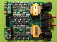
Your CLK line and your DATALR lines ...do they run in parallel ? At what distance are they.
This is the noise of the Chinese non-balanced version.Yeap I can hear it. I find it interesting that with increase of DSD frequency , noise increases.
Your CLK line and your DATALR lines ...do they run in parallel ? At what distance are they.
My versions are balanced and this noise is not there.
Attachments
Is the volume of music is adjustable by Signalyst HQ player or an atenuator is required?
HQ Player has a volume control option.
In Linux, HQPlayer can precisely adjust the volume through ALSA. On Windows did not check.
Worked for me in Win10 too with my earlier NoDac projects.
Today I've been listening to one of ppy's DSC2 boards.
I've temporarily assembled the DSC2/Amanero onto an old aluminium base and I'm feeding it with some TPS7A4700 power supply modules. DSD256 data into the Amanero (firmware version 2003) is courtesy of HQ Player, upsampling CD quality FLAC rips and routed via an HQ Player NAA.
The sound is outstandingly good; rich and very detailed, kind of natural/organic. My partner is a musician but pretty ambivalent about my 'tinkering' but the sound immediately caught her attention and she was soon asking me to put various tracks on; we spent several hours just going through the music library.
Did I mention that there is no extraneous noise too, nor any of the pops/clicks that can affect this sort of DSD replay.
A great job ppy - thanks.
An externally hosted image should be here but it was not working when we last tested it.
Bit of a brain freeze but how would you implement 16 dual FFs to give a moving average filter?Yes you are correct WRT unity weighted elements. A good example is Sabre DACs.
I have a question for you Miska - would it not be better to use differential OP flip flops for a balanced design?
I'm wondering if the bulk of non linearities are due to inherent non RTZ nature of DSD stream. As such I would think the fastest dif OP logic would give best results. Something like 16 x Potato 74G74 dual FF should work well.
Otherwise is it possible to integrate RTZ coding?
Terry
If I understand correctly about the inter symbol interference issue (non RTZ issue) of DSD - it's the result of the finite fall time of the logic which results in some residue of the high signal pulse energy still existing at the next data period? In the case of a moving average filter, I'm not sure how it affects the final analogue signal - doesn't a moving average filter result in an analogue signal which is somewhat smooth out & does this smoothing not result in the same effect as residual pulse energy overflowing from one data period to the next? Having said that, is the measured increase in THD+N when higher samplerate DSD was used reflect this ISI issue? Any thoughts?
Faster o/p logic (faster rise/fall times) would reduce this residue to some extent but I'm still trying to get my head around how all this plays out in a moving average style filter?
Introducing RTZ between DSD samples seems to be the way to alleviate the problem entirely by upsampling the signal introducing 0 value samples between samples. Bruno Putzeys mentions this issue & references the CS4303 DAC as the first commercial implementation of this DSD RTZ
Return-to-zero coding is utilized where each oc*curence of a 1 is 75% high and returns low for 25% of the bit period as shown ip. Figure 7. This technique ensures that the energy within each 1 includes the effects of finite rise and fall times regardless of the previous or next state and mini*mizes distortion.
From the datasheet, Figure 7 isn't very clear but I think it shows that the DSD stream is upsampled by 4? so that each logic high spans 3 clock ticks & the 4th is always a low. I'm not sure why they chose this upsampling - maybe it has something to do with the 30nS pulse width specified in the data sheet? Again, any thoughts?
Sorry, I knew I was being dumb - it takes 16 dual differential o/p FFs (Potatosemi FFs) per channel for the same number of taps per channel (32). I wonder if reducing the number of taps per channel to 16 unduly affects the sound quality? Has anybody tried lower number of taps? What's the sweet spot number of taps?
The potatosemi chips are expensive, $3. Does anybody know of other fast output dual differential FFs?
I also presume feeding the o/p pulse from 1Q into 2D as well as to the output resistor will not unduly affect performance?
Also, why wouldn't upsampling by 2 work to insert RTZ into DSD data stream?
The potatosemi chips are expensive, $3. Does anybody know of other fast output dual differential FFs?
I also presume feeding the o/p pulse from 1Q into 2D as well as to the output resistor will not unduly affect performance?
An externally hosted image should be here but it was not working when we last tested it.
Also, why wouldn't upsampling by 2 work to insert RTZ into DSD data stream?
Last edited:
Sorry, I knew I was being dumb - it takes 16 dual differential o/p FFs (Potatosemi FFs) per channel for the same number of taps per channel (32).
Yes, that's right
")
I wonder if reducing the number of taps per channel to 16 unduly affects the sound quality? Has anybody tried lower number of taps? What's the sweet spot number of taps?
Who knows? I think more taps = higher dynamic range. Same goes for lower value resistors, but the tradeoff is likely more distortion for lower value resistors.
The potatosemi chips are expensive, $3. Does anybody know of other fast output dual differential FFs?
All the usual suspects just look up 74HC74 etc Maybe a 5V tolerant part would be good to increase OP swing / current. Having said this the Potato parts look very good.
I also presume feeding the o/p pulse from 1Q into 2D as well as to the output resistor will not unduly affect performance?
Shouldn't matter as OP change of state is triggered from rising edge of clock. As long as clocks are adequately buffered / fanned out should be OK.
An externally hosted image should be here but it was not working when we last tested it.
Also, why wouldn't upsampling by 2 work to insert RTZ into DSD data stream?
With RTZ coding, theoretically every pulse has an equal amount energy from the rise / fall component. So it should cancel out. Then the only non linearities will be a/ variance of rise fall time (should be very small) and variance of 'On' and 'Off' resistance due to varying OP loading.
This is why a virtual ground is optimum for this type of DAC. All the 'Ons' are the same and all the 'Offs' are also the same load for logic switching elements.
It took me a little while to get my head around this but it is simple logic....
You can see this non linearity for example in Sabre performance specs 'voltage out' versus 'current out'. They are essentially the same but in voltage out the logic switching the resistors sees variable load and increases distortion.
T
@mmerrill69 & zenelectro: Just some practically oriented remarks to your FF & RTZ considerations:
1. In the The Well-Tempered MC thread one of the builders exchanged an LVC7404 squarer inverter with a potatosemi version and found that the sound was audibly better. So maybe Potatosemi somehow and in some respect has an edge here ... ?
2. Some years ago I tried building a very simple DSD output (balanced FF & RC filter) and measuring the distortion of the Potato 7474 I noticed that it began rising around 1 mA output current. I would have hoped that it would had been possible to load it more without distortion.
3. Again some years ago I read a bit about DSD and noticed that it is quite jitter sensitive. To this end I have been looking for a low jitter (close-in phase noise) FF and not yet able to measure it have concluded that at least the basic 74HC04 - inverter that is - necessarily must have a reasonably low jitter level as Herbert Rutgers in his oscillator was able to reach ~- 131 dB sqrtHz at 10 Hz. Don't know if the 74HC74 is similar - but the hope is green I guess ;-)
One parameter I reckon matters at least WRT jitter is the voltage supplied to the logic in question.
And then there's the question of the resistors used ... I might be mistaken here but my guess would be that these circuitries may reach a quality level reflected by the sound quality of the resistors used ... And to this end: If someone knows of an equal sound quality replacement for the TX2575 or Charcroft CARs then I'd be most interested in hearing about it ...
Cheers,
Jesper
Hi Jesper,@mmerrill69 & zenelectro: Just some practically oriented remarks to your FF & RTZ considerations:
1. In the The Well-Tempered MC thread one of the builders exchanged an LVC7404 squarer inverter with a potatosemi version and found that the sound was audibly better. So maybe Potatosemi somehow and in some respect has an edge here ... ?
2. Some years ago I tried building a very simple DSD output (balanced FF & RC filter) and measuring the distortion of the Potato 7474 I noticed that it began rising around 1 mA output current. I would have hoped that it would had been possible to load it more without distortion.
Read my reply above WRT running into virtual ground. There is mechanism of non linearity with OP voltage swing. When FF goes high, if there is swinging voltage on OP of resistor network (or even 1 resistor) the 'on' resistance of FF will change according to current. This will result in distortion. If the resistor is driven into virtual ground, each 'on' and 'off' (high and low) will see exactly same current.
FWIW 1mA is a lot of current. If you take Sabre, each unity weighted 'bit' is a 50k resistor and so the current is micro amps.
Straight inverters can have very low phase noise.3. Again some years ago I read a bit about DSD and noticed that it is quite jitter sensitive. To this end I have been looking for a low jitter (close-in phase noise) FF and not yet able to measure it have concluded that at least the basic 74HC04 - inverter that is - necessarily must have a reasonably low jitter level as Herbert Rutgers in his oscillator was able to reach ~- 131 dB sqrtHz at 10 Hz. Don't know if the 74HC74 is similar - but the hope is green I guess ;-)
http://www.ham-radio.com/sbms/LPRO-101.pdf
check page 18 for comparison of various squaring circuits. 74AC04 does not degrade Wenzel ref OCXO at 10Hz offset. LVC or Potato should be better again. I'm not sure how much more jitter FF adds. It's also determined by power supply as CMOS have poor PS rejection.
Probably to do this really well you need separate VLN reg for each FF or at a minimum, very good decoupling for each FF.
One parameter I reckon matters at least WRT jitter is the voltage supplied to the logic in question.
I'm not sure about that. Prop delay goes down as supply voltage goes up. Worth checking data sheets.
And then there's the question of the resistors used ... I might be mistaken here but my guess would be that these circuitries may reach a quality level reflected by the sound quality of the resistors used ... And to this end: If someone knows of an equal sound quality replacement for the TX2575 or Charcroft CARs then I'd be most interested in hearing about it ...
I think the resistors probably matter the least compared to other issues. As long as they have decent tempco.
T
Good info, Zen & Gentle
@Zen
It does, however give the rise/fall times of 0.8nS which seems to be one of the critical factors & this info is missing from a lot of other FF datasheets so it makes comparisons difficult. I guess low propagation delay is an indicator of fast rise/fall times.
Zen, can you say more about how virtual ground might be implemented in a weighted average scenario - I presume this requires an active I/V stage but how is averaging achieved?
@Gentle, good info on the increased distortion > 1mA output & the jitter info about Rutgers clock
@Zen
It's a pity the Potato datasheets don't have the same information seen in other FF logic datasheets such as current output?All the usual suspects just look up 74HC74 etc Maybe a 5V tolerant part would be good to increase OP swing / current. Having said this the Potato parts look very good.
It does, however give the rise/fall times of 0.8nS which seems to be one of the critical factors & this info is missing from a lot of other FF datasheets so it makes comparisons difficult. I guess low propagation delay is an indicator of fast rise/fall times.
I was more thinking of the exact factor you touch on later - the variation in resistance that the o/p pulse is feeding into when it is routing to the o/p resistor AND the input Data pins.Shouldn't matter as OP change of state is triggered from rising edge of clock. As long as clocks are adequately buffered / fanned out should be OK.I also presume feeding the o/p pulse from 1Q into 2D as well as to the output resistor will not unduly affect performance?
Zen, can you say more about how virtual ground might be implemented in a weighted average scenario - I presume this requires an active I/V stage but how is averaging achieved?
@Gentle, good info on the increased distortion > 1mA output & the jitter info about Rutgers clock
@ppy Do you mind to share the KiCad files?
I have some Jensen 1:1 transformers I'd like to use for a balanced build.
@ppy
I am always a diyer and I would like you to share the same thing to me.
Thanks so much.
- Home
- Source & Line
- Digital Line Level
- Signalyst DSC1