Debian for server and Elementary OS for desktop.
I am testing this configuration, I was especially surprised by Elementary OS, I did not know it, it is really fast and fluid. so far.
I have used windows 10 as a server and remote (I can continue using it because they are on the same computer). In Pavel's favorite configuration there is more detail than with windows10, better stereo image and more bass. But I have the impression that the sound is more muted than with windows 10. I wonder if Amanero and Linux have something to do with this and is there any ideal configuration for Amanero.
I wonder if any additional optimization settings are needed in the operating systems
I apologize. My English is very far from perfect.🙂not sure if grasped 100% what you meant by your answer.
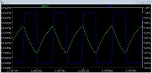
The DSC resistive matrix is a dynamically changing load of ~15mA. The registers also at the time of switching create high-frequency interference on the power board. My voltage regulator does this efficiently.
DSC voltage regulator and load current +-10mA/50kHz:
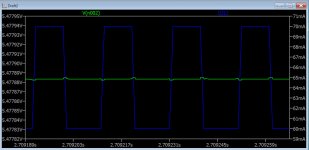
LT3042 voltage regulator and load current +-10mA/50kHz:
DSC2 is developed under the OpenHardware license. Post your changes. This will help the project develop.I was asking you about it because i have subjectively felt a big improvement when i have by-passed the 5v onboard regulators and hooked up salas reflektor's for the output stage. Maybe is worth trying along your quest for the "perfect" DSC.
Interesting remark. I thought no one would notice.😀Another thing, a little nerdy... but i can't resist. on the photo you have posted some time ago of the newer version, i have seen that you have removed (or at least, that seems on the photo) the soldermask on top of the clk line. I always considered that an "extreme" measure to put in place when signal is well over Ghz... And also, you need to proceed on that with a grain of salt, more time than others the ENIG finished can degrade the signal more than the soldermask. not sure if that is a trick needed in such "low" frequency domain as it is the one in the DSC topology... but that is just a speculation 😱
Yes, indeed at 49 MHz this design should not do much better. But I will leave it exactly as it is. This design has some commercial and aesthetic appeal. If you want to get a gerber without this design, I will provide it to you.
4 layerThe board will be 2 or 4 layer ?
Attachments
i am eager to see the schematic to "rob" some great ideas from you.
I am in the process of developing a sort of DSC "stick" that leverages a McFifo in front of it.
Obv will be under OH and the DSC project will be cited...
Curiosly, without knowing what we are doing... it seems they ended up quite similar.
"dual mono" layout for me
I am in the process of developing a sort of DSC "stick" that leverages a McFifo in front of it.
Obv will be under OH and the DSC project will be cited...
Curiosly, without knowing what we are doing... it seems they ended up quite similar.
"dual mono" layout for me
Attachments
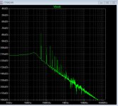
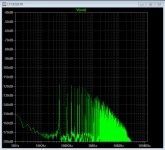
Pavel, your simulated 3042 output shows 10mohm Zout, and, more importantly, the FFT starts to fall very fast.
May I ask at what standby current did you do the simulation?
I have real life outZ measurement for 3045 ~5mohm min, and less than 20mohm out to 2MHz bandwith almost without a resonant peak. All this with 10uF effective capacitance on the output.
Other, more refined results show that lt3042 can go below 1mohm, below the 10kHz range.
On the other hand, having 40-60dB less than 10mohm Zout is in the 10/100uohm range. In all honesty, I would like to see real life measurements, up into the MHz land, of such results..
I understand that your topology 'could' achieve that level, in theory, but real life trace impedances, stray inductances and capacities will make it a real hm.. adventure. Your array is not a small area, how do You intend to distribute the regulator output with low impedance?
Ciao, George
Thanks!
This is an excellent topic for further exploration here. I have corresponded with many working with variations on the DSC scheme who suggest that the power supply's ability to respond to the needs of the shift registers is critical to the final performance. I look forward to hearing more from those who have tried different approaches. As an aside, i have heard from few digital engineers who I trust that the LT 3045 style regulators are not the best choice for powering, say, clock circuits, because of output impedance, settling, transient capabilities, etc.
I am not all that well versed in tis, but what regulator can really be expected to perform all that well at over 20 MHz?
Pavel, your simulated 3042 output shows 10mohm Zout, and, more importantly, the FFT starts to fall very fast.
May I ask at what standby current did you do the simulation?
I have real life outZ measurement for 3045 ~5mohm min, and less than 20mohm out to 2MHz bandwith almost without a resonant peak. All this with 10uF effective capacitance on the output.
Other, more refined results show that lt3042 can go below 1mohm, below the 10kHz range.
On the other hand, having 40-60dB less than 10mohm Zout is in the 10/100uohm range. In all honesty, I would like to see real life measurements, up into the MHz land, of such results..
I understand that your topology 'could' achieve that level, in theory, but real life trace impedances, stray inductances and capacities will make it a real hm.. adventure. Your array is not a small area, how do You intend to distribute the regulator output with low impedance?
Ciao, George
This is an excellent topic for further exploration here. I have corresponded with many working with variations on the DSC scheme who suggest that the power supply's ability to respond to the needs of the shift registers is critical to the final performance. I look forward to hearing more from those who have tried different approaches. As an aside, i have heard from few digital engineers who I trust that the LT 3045 style regulators are not the best choice for powering, say, clock circuits, because of output impedance, settling, transient capabilities, etc.
I am not all that well versed in tis, but what regulator can really be expected to perform all that well at over 20 MHz?
Duh.. Short answer: none.. 🙁
Regulation serves to generate a precise, stable DC output. At low frequencies it should be providing also low impedance 'by design', that is due to high negative feedback in the circuit.
It is extremely difficult to provide high gain bandwith product, that is high open loop gain up to high frequencies.
But it also should be not necessary. At high frequencies only the local bypass schemes can provide low impedance.
The dropping open loop gain with frequency will always result in rising output impedance, after the feedback loop is closed. Such a circuit behaves like an inductance, looking into it's output. This virtual output inductance than should be combined carefully with the bypass capacitances in the scheme. The transition zone is frequently showing impedance peaking, beacuse of the parallel resonance of the cap with the regulator virtual output inductance.
A good design is capable to resolve this peaking in the smoothest way.
That means the right amount of damping in the circuit, which contradicts to our lowest possible output Z requirement..
Higher output Z regulators are 'handing over' from the active regulation zone to the passive local bypass caps in a smoother way, much less peaking.
So I think optimum design needs to get right this balancing act..
And I would like to 'rebounce' your question:
What local bypass structure can be applied AT ALL, to extend above 20MHz... 🙂 🙂
That is a much tougher question..
Ciao, George
Last edited:
Thanks George, I was aware that the local bypass structure would be more relevant to the ultimate reponse at high frequencies. I look forward to reading/learning more from others on this topic as it applies to the DSC circuit as well.
One other thing, I am aware of generous amounts of feedback being the way that most regulators achieve low Z out. I never seem to hear any discussion about alternative regulators: Ayre, for example, claims to use no feedback for the discrete regulators used in their products... this seems to be a very unusual approach though, and I suspect proprietary, so I do not think we will see Ariel Brown (Ayre lead engineer) showing up here to discuss such.
One other thing, I am aware of generous amounts of feedback being the way that most regulators achieve low Z out. I never seem to hear any discussion about alternative regulators: Ayre, for example, claims to use no feedback for the discrete regulators used in their products... this seems to be a very unusual approach though, and I suspect proprietary, so I do not think we will see Ariel Brown (Ayre lead engineer) showing up here to discuss such.
Salas..
'Natural ' low impedance in silicon means high current.
Of which a natural 'prophet' is Salas here.. 🙂
Ciao, G
'Natural ' low impedance in silicon means high current.
Of which a natural 'prophet' is Salas here.. 🙂
Ciao, G
Ayre, for example, claims to use no feedback for the discrete regulators used in their products... this seems to be a very unusual approach though, and I suspect proprietary, so I do not think we will see Ariel Brown (Ayre lead engineer) showing up here to discuss such.
From what I recall, when Charlie Hansen spoke about feedback he was meaning global feedback. So to him, an EF based regulator hasn't feedback whereas to most EEs it does have. I think he favoured EF-based regs but my memory is rather shaky.
As already stated before... the Reflektor (a type of salas shunt) made a big difference on the sound.
UBiB
Have you tried the Salas UBiB?
As already stated before... the Reflektor (a type of salas shunt) made a big difference on the sound.
Have you tried the Salas UBiB?
Have you tried the Salas UBiB?
i have 4 channel (2positive and 2negatives) of the Ubib 1.3 serving my preamp at the moment, and they sound as no others (... of course among all the one i have tried in that spot).
Never thought using them on the DSC because they require a little tweaking to be able to deliver with such "low voltage" of 5volts.
i have still some channels to spare from the last gb, maybe i will give them a try.
Btw, the Reflektor-D (that are very optimized for low voltage applications) at the moment supplies 1 the left output, 1 the right output, 1 the McDualXo (total bypass of the on board regulators) and 1 the McFifo (in this area i will switch to a more conventional and less power hungry solution... there's no real benefit to supply the mcfifo with such "clean" supply because of the topology involved).
As far as i know 2 thing matter in power supply.
Noise and output impedance. both needs to be low for smooth operation.
To measure both is hard;
YouTube
I guess none of us have any idea about output impedances of ldo's which are not stated in datasheets.
have you tried LT4320 ldo to power up your device instead of ubib. The common mistake made is using large cap out of it. 10uf is enough most of the time.
I also read that LM3117 have lower Zout thank LT42xx series
________________________________________________________
I am glad if any expert like pavel explain us why discrete regulators performs better than LDO's in analog circuits acc to some of user experiences.
Last edited:
there's an handy comparison chart about Zout of various regulators attached to the "super regulator" in the diyaudio store.
salas shunt are among the best about the output impedance.
and noise, well... many has tried without success to measure it, because it is so low that needed proper instrumentation that is not easily present among us hobbists.
about your question... no, i have not ever used the 4320 to supply the output stage, neither the lm3117.
In that topology is mandatory to have very low noise plus a rock-solid regulation, every "jitter" in the voltage became noise at the output and thus reduce the SNR.
to be precise, absolute voltage value can vary during a session, but must be consistent between samples.
Supported from what i heard, shunt will not leave my dsc soon 😀
Last edited:
there's an handy comparison chart about Zout of various regulators attached to the "super regulator" in the diyaudio store.
salas shunt are among the best about the output impedance.
and noise, well... many has tried without success to measure it, because it is so low that needed proper instrumentation that is not easily present among us hobbists.
about your question... no, i have not ever used the 4320 to supply the output stage, neither the lm3117.
In that topology is mandatory to have very low noise plus a rock-solid regulation, every "jitter" in the voltage became noise at the output and thus reduce the SNR.
to be precise, absolute voltage value can vary during a session, but must be consistent between samples.
Supported from what i heard, shunt will not leave my dsc soon 😀
what a great info thanks.
Hmmm.
I have not tried Reflektors on my DSC-2 because I was worried about possible oscillation caused by the significant capacitance on the DSC-2 power rails. Have you checked for oscillations with your Reflektor powered DSC with a 'scope?
I even have a pair of Reflektors set up for 5 VDC here which I could try, but I ma hesitant to do so because of my fear of oscillations. IME the Salas regs do not like to see much C on their output (the uBiB is bit better in this regard).
there's an handy comparison chart about Zout of various regulators attached to the "super regulator" in the diyaudio store.
salas shunt are among the best about the output impedance.
and noise, well... many has tried without success to measure it, because it is so low that needed proper instrumentation that is not easily present among us hobbists.
about your question... no, i have not ever used the 4320 to supply the output stage, neither the lm3117.
In that topology is mandatory to have very low noise plus a rock-solid regulation, every "jitter" in the voltage became noise at the output and thus reduce the SNR.
to be precise, absolute voltage value can vary during a session, but must be consistent between samples.
Supported from what i heard, shunt will not leave my dsc soon 😀
I have not tried Reflektors on my DSC-2 because I was worried about possible oscillation caused by the significant capacitance on the DSC-2 power rails. Have you checked for oscillations with your Reflektor powered DSC with a 'scope?
I even have a pair of Reflektors set up for 5 VDC here which I could try, but I ma hesitant to do so because of my fear of oscillations. IME the Salas regs do not like to see much C on their output (the uBiB is bit better in this regard).
Salas himself confirmed that Ref-D not likes caps on its output.
I have not tested with an oscilloscope how they are behaving at the moment. And back when i hooked them up i have not tought about the capacitance problem due to the nature of the input filtering of each SR.
Before the caps you have an inductor that reduces the "short-a-like" behaviour that a caps excerts.
Tomorrow i will check to make sure that this supposition holds up.
I have not tried Reflektors on my DSC-2 because I was worried about possible oscillation caused by the significant capacitance on the DSC-2 power rails. Have you checked for oscillations with your Reflektor powered DSC with a 'scope?
I even have a pair of Reflektors set up for 5 VDC here which I could try, but I ma hesitant to do so because of my fear of oscillations. IME the Salas regs do not like to see much C on their output (the uBiB is bit better in this regard).
just checked.. no oscillations here
Thanks...
Good to know, I'll give my RefleKtors a try then.
just checked.. no oscillations here
Good to know, I'll give my RefleKtors a try then.
Good to know, I'll give my RefleKtors a try then.
that would be great.
i felt a big improvement... wish to know if you will have the same benefit.
- Home
- Source & Line
- Digital Line Level
- Signalyst DSC1