I spoke to Canterbury windings about the production of EI transformers and this was their response
Dear James,
Unfortunately I don’t make EI core transformers + I am reluctant to recommend anyone as last time that I did my customer told me that the quality was poor from the recommended manufacturer
Dear James,
Unfortunately I don’t make EI core transformers + I am reluctant to recommend anyone as last time that I did my customer told me that the quality was poor from the recommended manufacturer
Yup, if you measure the DC offset across and POS and NEG and it's real small like that (mine is 0.007v and 0.009v) then there shouldn't be any issue running direct from these without coupling caps, especially if you have an amp with inline coupling capacitors like many valve amps do.Ok, here’s one for you. I’ll probably be shot for suggesting this. But it’s been bothering me that with only using single-ended output I’m in affect only using half the power/gain output of the DDDAC, by connecting either ENG or POS and common and I could do with a bit more gain anyway. I was also curious about the amount of DC de DDDAC produced. Well in my case it was 0.008Vdc&0.000Vdc R/L respectively. So I thought what the heck, it will be a nice experiment to do away with the output buffer caps and since I knew Rload resistance in my power amp (I put it there), I got rid of Rload in the DDDAC too. So now I’ve connected POS/NEG single-ended RCA out to my amp. I’m sitting here listening to it now and I can not put any fault to it, if anything it sound better with +/-15Db more gain (someone will be able to do the math on this). I also made change to my PSU so it’s hard to tell what’s what but less is more in my book & no output caps..
Any comments?
I have mine running like this now since the weekend and it sounds really good.
The only downside I have found is that with the increased gain, I get a little clipping on my amp if I put the volume up very loud. I guess it's over the 380mv sensitivity on my amp's input, but as long as I keep it attenuated to a sensible volume, it sounds much better than with coupling caps, especially the cheap ones I had in there 🙂
..... it sounds much better than with coupling caps, especially the cheap ones I had in there 🙂
.. Glad to hear I'm not the only one.. My First watt F5 is coping fine , no clipping so far, and it's "cap"less all the way from DAC chip to driver..! 🙂
You could try a little attenuation to bring down the gain. Just now, I have Rload (at the amp end) 47K between pos/neg and 4k7 inline, to give you an idea.
JFET Buffer Circuit
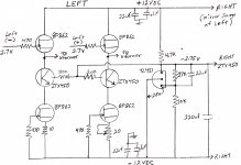
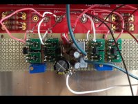
Attached are a schematic and photo of my BF862 JFET buffer. There is almost too much detail. I could hear the valves and mechanical linkage of a bassoon clacking on a Vivaldi recording through my Grado GS1000 headphones – something I have never heard before. The break-in period was UGLY at times and bad recordings are punishing. The best CDs sound amazing. I am going to test HF filter capacitors on the DDDAC outputs to try to soften the SQ a hair. I don’t need to hear each 0 and 1 from the CD. This buffer can pass a signal greater than 100 MHz.
This Buffer is for the masochistic DIYer. It requires testing and matching of BF862 JFETs. A negative power supply is needed. Surface mount components require more care. Nevertheless, a buffer is the only alternative for the person who wants to totally tweak out a single board DDDAC and drive an output transformer without compromising the musical experience. On the positive side, all semiconductors and resistors are inexpensive and available as SOIC-23 surface mount. The BF862 is only available as a SOIC-23. Anyone want to design a surface mount PCB for this buffer? I could provide a set of components with matched BF862s. Maybe Doede could drop the buffer circuit into the main board foil trace for optional use in a future revision.
The circuit uses the ZTX450 which is used in the highly acclaimed Pearl 2 DIY phono preamp to provide a constant voltage source for the 1st JFET gain stage. The ZTX450 makes the lower BF862 constant current load - more constant, and allows a more standard -12VDC power supply to be used. My prototype uses a mixture of surface mount and standard size components. The TL431 regulates the voltage to the base of the ZTX450s. The 20 ohm pot is used to zero out the voltage offset between the + and – outputs to the transformers.
If the ZTX450s and the TL431 and its associated components are eliminated, you end up with the Nelson Pass B1 direct coupled buffer design which should sound a bit more euphonic. It would be much simpler and fit easier into Doede’s main board. My 2SK170 version of this sounded great, but I’m a masochistic DIYer.
Attachments
Carlsor, do you have a basic explanation of what that is and what it does and how it's better than either an output transformer, a good coupling cap or simply using the pos and neg direct if the DC offset is low?
Buffer Explaination
dwjames,
The JFET buffer does not replace coupling capacitors or transformers - it is used to interface the DDDAC output with these devices. The Buffer load (JFET gate) to the DDDAC output is over 1meg ohm - almost nothing. The DDDAC doesn't see the transformers or capacitors or the load that they terminate to. Meanwhile, the Buffer follows the DDDAC output signal but provides its own power to drive the signal through these devices.
An electrical load can affect a signal source. The Cinemags interfere with some of the musical detail and dynamics from a single board DDDAC. Multiple boards help overwhelm the Cinemag and its load with a lower combined output impedance (ie stronger signal)
Its like the difference between a bicycle and military tank both moving at 20kph. The bicycle may be affected by the terrain, but the tank will move ahead unaffected. The Buffer is like a tank following the pedal speed of a stationary bicycle - both will operate uninhibited.
The Buffer pot adjustment is an opportunity to bring the DC offset even lower, but this is not the primary reason for using a buffer.
I hope this helps.
Last edited:
Excellent explanation, thanks 🙂
Makes me wonder as I have a spare SRPP valve output stage lying around...
Makes me wonder as I have a spare SRPP valve output stage lying around...
I hope someone has an explanation for this:
When I tried to use the balanced outputs directly without trannies or caps. The stereo image collapsed and I got a lot of extra bass. Totally not amused with the result.
Then I reconnected my output trannies and voila there it was back again. A nice wide stereo image with a lot of envelopment.
Do any of you know what could have been the problem? Did I do anything wrong?
I measured the DC offset. 2mV on the right channel and 0.3mV (very low) on the left channel. I connected the pin of the cinch plug to the pos en the sleeve to the neg terminal.
Any ideas?
Excellent explanation, thanks 🙂
Makes me wonder as I have a spare SRPP valve output stage lying around...
+1
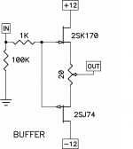
Would a buffer like this, from the VFET article, be fine?
Attachments
Stijn, one question, you are NOT using the Rload resistors? the Ra and Rb ones, that should not be possible, or do you mean you run it without the 100k bleeders which are normally after the capacitor? that would be perfectly correct to remove them. and no cap is the best cap of course !
thanks for the buffer circuit! nice idea and extra tweak opportunity. one question though, things like this are worthy an own thread if discussion start around the topology of the buffer stage. please do not dwell too much on it, or open an own thread for it. Sorry to police, but I want this thread to stay as much focused as possible on the dac it self. thanks for understanding...
Stijn, one question, you are NOT using the Rload resistors? the Ra and Rb ones, that should not be possible, or do you mean you run it without the 100k bleeders which are normally after the capacitor? that would be perfectly correct to remove them. and no cap is the best cap of course !
That's exactly what I was thinking, you should have your I/V conversion somewhere...
Oh, and sorry for going off topic...😀
Stijn, one question, you are NOT using the Rload resistors? the Ra and Rb ones, that should not be possible, or do you mean you run it without the 100k bleeders which are normally after the capacitor? that would be perfectly correct to remove them. and no cap is the best cap of course !
Hi Doede, you are right I was referring to not using the 100K (bleeder) resistor. I thought this was also referred to as the Rload resistor, or am I mixing things up? Can you comment on if what I’m doing is sensible with regard to effectivly connecting the DDDAC NEG to my AMP's ground, is there a danger in doing this?
Last edited:
I have a question. I have a four deck Dac. If I measure the resistance between the positive connections of the left and right channels (nothing else connected) I get a resistance of 68 ohms. Are they connected through the load resistors and a common ground plane? Otherwise, what is the explanation?
Thanks
David
Thanks
David
Hi Doede, you are right I was referring to not using the 100K (bleeder) resistor. I thought this was also referred to as the Rload resistor, or am I mixing things up? Can you comment on if what I’m doing is sensible with regard to effectivly connecting the DDDAC NEG to my AMP's ground, is there a danger in doing this?
as said the IV resistors are the four dales on the mainboard. they are needed for bias and IV conversion. the bleeder to referred to is only needed when capacitors are used
danger? depends, yes there might be.. if your chain is completely DC coupled, you might amplify DC. to your speakers if anything ever will go wrong with the dac. also not sure at start up if the DC offset is not higher, so it might plop or put DC to your speakers. if your amplifier has a circuit to protect your speakers for Tom much DC, than is there is no danger, your amplifier will switch off when it comes to an event where the DC offset is too high
I have a question. I have a four deck Dac. If I measure the resistance between the positive connections of the left and right channels (nothing else connected) I get a resistance of 68 ohms. Are they connected through the load resistors and a common ground plane? Otherwise, what is the explanation?
Thanks
David
yes you measure two times the Rload... which with four decks is 34 ohm, so 68.... they are connected through the common point
check the circuits ( from my download section ) you can also see it in there...
as said the IV resistors are the four dales on the mainboard. they are needed for bias and IV conversion. the bleeder to referred to is only needed when capacitors are used
danger? depends, yes there might be.. if your chain is completely DC coupled, you might amplify DC. to your speakers if anything ever will go wrong with the dac. also not sure at start up if the DC offset is not higher, so it might plop or put DC to your speakers. if your amplifier has a circuit to protect your speakers for Tom much DC, than is there is no danger, your amplifier will switch off when it comes to an event where the DC offset is too high
I did swap out the Dale's for some Caddocks (same value obviously).
I do measure a few more mVdc at start up of the DAC for a mere second or so, but I make a habbit of turning on the DAC before I turn on the amp. I'm not getting any plops, in that respect the DDDAC seems to behave much better then my old DAC in comparison. I'm not sure if my amp is DC coupled, but there are no caps in the signal path so I suspect it is.
Thanks,
Last edited:
I did a quick check and measured 24mVdc/4mVdc (L/R) at the speaker terminals, with no CAP and having connected POS/NEG to single-ended RCA out . Which is a little more than I would have wished for on the L channel. I’m afraid this will kill the microdynamics of the left channel.
Would there be any objections against using a cap on the POS side and connecting the return to the NEG side (including the bleeding R again)? This way I might achieve a higher gain, then connection POS/common and still be able to surppress DC?
Would there be any objections against using a cap on the POS side and connecting the return to the NEG side (including the bleeding R again)? This way I might achieve a higher gain, then connection POS/common and still be able to surppress DC?
I've just done the done the psu mod I.e. Shorted R1 and R2 and the fuse, and am pleased with the results. Now the two reservoir caps (4700uF) are in parallel, I was thinking of replacing them with a single four pole mundorf 10000uF. Any reason why this isn't a good idea? Or has anyone used any four pole caps with this DAC?
Cheers, Si
Cheers, Si
- Home
- Source & Line
- Digital Line Level
- A NOS 192/24 DAC with the PCM1794 (and WaveIO USB input)