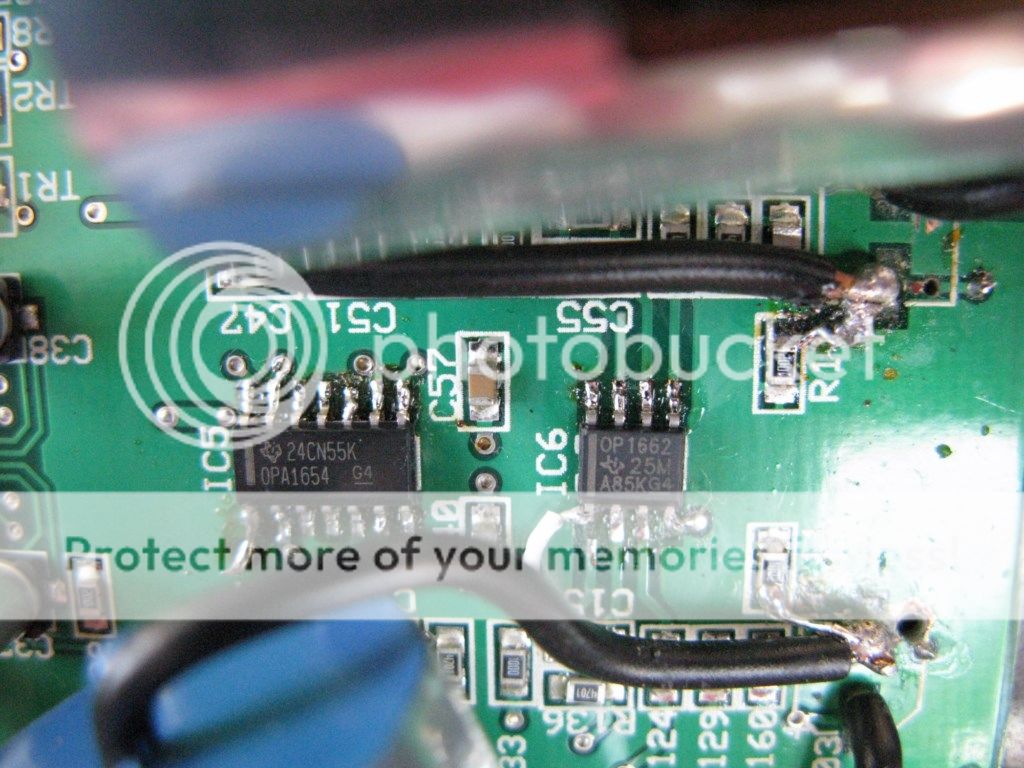
I'm wondering if anyone can help with selecting a compatible op-amp, or give guidance on re-working the loading around the op-amps, in the V-DAC2? I've done some Op-amp rolling, but i'm no depth expert on compatibility - i'm an enthusiastic DIYer. Here's what i've done:
Original Musical Fidelity spec in the circuit is a 4-channel 33079 (ST Electronics) followed by a 2-channel 33078 (ST Electronics).
First I replaced the DC Blocking caps by the RCA outputs: 47uF SMD with Nichicon ES 470uF Electrolytics (there is just room inside the case!).
Then to the opamps: I replaced the 2-channel 33078 ouput opamp with 2 x OPA827 on a Browndog. Lovely improvement in detail, whilst keeping the 'musicality'.
Then I got excited and replaced the 4-channel 33079 with an LME49740. But the bass just disappeared - almost like a low frequency filter. Really not sure why (could it be the larger current requirement of the 49740 at 18.5mA, versus the 8mA of the 33079?). So I switched the 49740 to an OPA1644. Bass came back with good detail and spaciousness. However, over time (i.e. a few hours) the sound became relatively fatiguing. Seemed tight and clinical - it lacked the musical warmth, despite representing instruments accurately.
So I decided to switch the 2xOPA827 on Browndog with an OPA1642. Now this should be a happy result, and mostly it is the best sounding so far (i.e. the combination of OPA1644 and OPA1642 in the circuit), but the mid bass has dropped away again - significantly reduced - coming back with deeper bass notes being present, although softer.
Can anyone give me some guidance of whether this is just audio character of this op-amp series, or is there likely to be an incompatibility with the audio circuit leading to the reduction in mid-bass? It was interesting that i saw this effect with both the 49740 and then the 1642, which are both in different locations. I have an OPA1612 ready to test, and i can go back to the ST chips, although they are not my first choice - they are musical but after hearing the depth of detail produced by the others i've been testing, i'm loath to go back! Any ideas anyone?
Will
I think i've answered my own question: i went back to the OPA1642, but used 2 x OPA1641 chips instead on a Browndog. Then the solution to the bass: 0.1uF decoupling caps across the supply pins - really sorted the bass and balances the presentation generally.
So, if you're interested in upgrading the V-DAC2 opamps, i recommend the 4-channel OPA1644 and the 2-channel OPA1642, with 0.1uF decoupling caps on the supply pins of each one - sound is more transparent than stock, but maintains that musicality.
So, if you're interested in upgrading the V-DAC2 opamps, i recommend the 4-channel OPA1644 and the 2-channel OPA1642, with 0.1uF decoupling caps on the supply pins of each one - sound is more transparent than stock, but maintains that musicality.
Hi wiland1,
how easy (smd?) do you think it is to completely bypass the analog stage and use custom I/V ? Can you post some pictures so I can see how it looks in that area ?
Also, did you change anything about the power supply ? Or are you using the stock wall wart ?
I am seriously considering this DAC and would like to get some feedback on it.
It's a great sound out of the box - i just like tweeking ") I'm using the stock wall wart supply - i'm sure the V-Dac supply would clean it up further.
I'm using the stock wall wart supply - i'm sure the V-Dac supply would clean it up further.
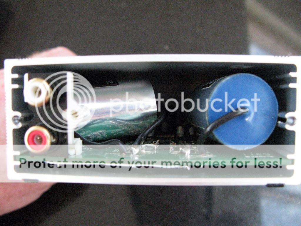
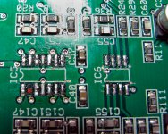
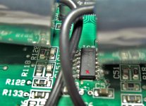
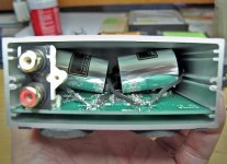
Only trouble is that i think those new OPA's are not totally happy - still slightly bass shy and harsh treble now (oscillating). As you can tell, i'm not a pro so cannot answer your questions. Here's a couple of photos:
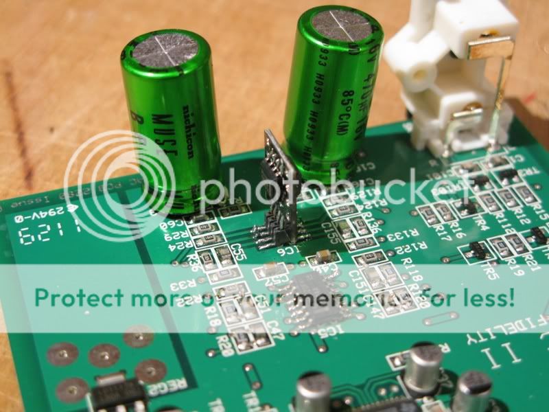
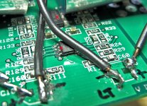
And one of the underside with the dead-bugged PP Panasonic caps on the supply pins
 :
:
I'll try and take a photo of the whole board from above so you can check it out.
I've got some 4.7uF PP Claritycaps on order now - the VDac Mod thread on the forum suggested this would be a better option than a big Elec Cap. I wonder if that is the reason my bass is not right? I had heard that a big EC is a good solution for signal path DC blocking - it's the small value ones which veil the sound...
I'm using the stock wall wart supply - i'm sure the V-Dac supply would clean it up further.Only trouble is that i think those new OPA's are not totally happy - still slightly bass shy and harsh treble now (oscillating). As you can tell, i'm not a pro so cannot answer your questions. Here's a couple of photos:
And one of the underside with the dead-bugged PP Panasonic caps on the supply pins
I'll try and take a photo of the whole board from above so you can check it out.
I've got some 4.7uF PP Claritycaps on order now - the VDac Mod thread on the forum suggested this would be a better option than a big Elec Cap. I wonder if that is the reason my bass is not right? I had heard that a big EC is a good solution for signal path DC blocking - it's the small value ones which veil the sound...
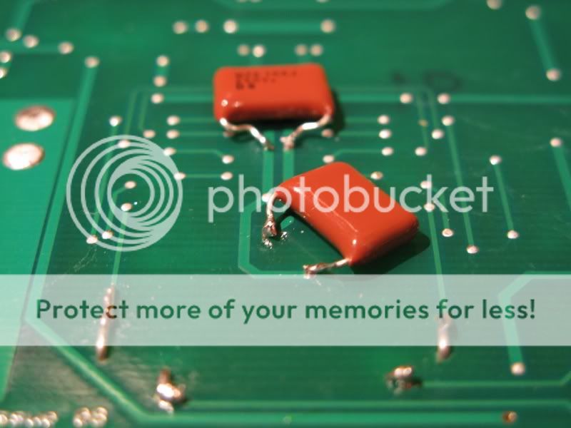
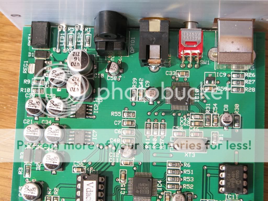
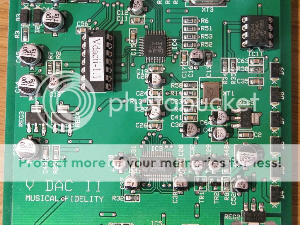
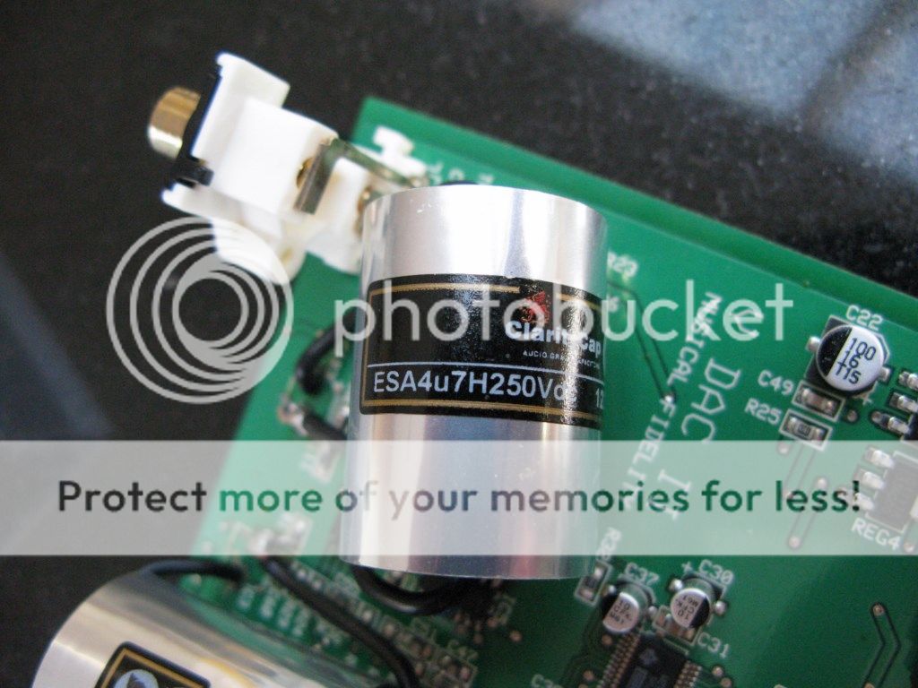
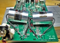
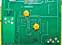
Here are 3 pics of the board for folks to look at - the three photos effectively stitch together. I've just replaced the 2 x 470uF green Nichicon ES Electrolytics with 2 x 4.7uF Claritycap PP caps from Falconacoustics - they're big and only just fit - and it sounds fabulous. Really clean, natural, balanced sound now, with lots of space around insruments. And it's still running in! So the advice about using PP caps in the signal path appears to be very true - if you can make them fit .
.
Last edited:
Hi Marvin - I cannot remember for sure, so i'll take the cover off and have a look this evening just to be sure - i'll post up another photo for you. What you describe sounds exactly right - i used the biggest ClarityCaps i could get in there
Since the post, i also experimented with the output Opamp and i am pretty sure i ended up with the OPA1662, which sounds beautiful, but let me check.
Will
Since the post, i also experimented with the output Opamp and i am pretty sure i ended up with the OPA1662, which sounds beautiful, but let me check.
Will
Hi Will, thank you for your response. I would really appreciate the photo as a reference. This morning I ordered from Mouser the OPA1642 and 1644, one each. From PartsConnection I ordered ClarityCap ESA 4.7uf/250v, 2 each.
I have searched all over the WEB and it seems few people have modded their V-DAC 2. So I was really pleased to find your post. I'm not a tech or EE, I just copy from others; so far so good. After I finish with the opamps I'm going to find a way to change the RCA connectors. It seems a bracket would need to be attached to the board were they are are now. There's room to do it. We'll see.
Regards,
Marvin
Hi Marvin - I can't tell you what a difference it made to the sound. running an ipod classic through this modded VDAC2 is really stunning. Forgive the state of the board in the pics - it's had a lot of opamps on and off! you can see that the ClarityCaps are tight in the case, but so long as their wires are well anchored by solder on the board (and you will need to drill holes in the board for them), they do not need a bracket - they hover just above the PCB and although they touch the sides of the case, I've never suffered any vibration related issues in the music.
As for Opamps, well this is where I came out: The OPA1654 and OPA1662 are definitely better sounding than the 1644/1642 - you'll have to order them! The 1662 is very musical and detailed. The 1664 was not available when I ordered, so I went for the 1654 and am not disappointed. It's cousin the 1652 is a terrific sounding opamp - slightly warmer than 1662, so I guess I just like the sound of the 1654/1662 combo. The 1642/1644 are fine, but they do not present the music so clearly or naturally by comparison.
Take care when you take out the old opamps - after 3 changes, the solder pads were in a really bad way, so you can see I had to solder a little jumper wire! Best of luck and would love to know what you think.
I just re-read your post and you mention the RCA connectors - I did change mine for some nice, chunky Cardas Gold connectors, but they made no discernible difference in the sound and they were a pain to get on and off (for accessing the internals) because they were bolted to that end-plate. I returned to the original MF connectors.
Will great pics, thank you. I'll post some too when I finish.
Questions:
1. When I desolder the SMD's (caps) at IC5 and IC6 to solder in the replacement caps and the solder pad is still intact then it's not necessary to drill holes is there? I can just solder to the pads can't I?
2. After the opamps are soldered in I would flip the board and solder a .1 ceramic cap to the supply pins of each opamp?
Best,
Marvin
Hi Marvin, to answer your questions:
1. In theory, you can just solder to the pads. In practise, those new caps are big and have heavy guage wire, so i suggest that they need better anchoring to the pcb. I drilled a hole next to the pad so that the cap wire had a tight fit, and then made a solder connection from the wire to the pad across the the top of the board - not very neat, but does the job. You may find a neater solution!
2. Exactly correct - between the supply pins. I really like the Panasonic poly caps you see in one of the photos, because they are a slim pillow shape and fit really snuggly against the underside of the board. This means you can change opamps without moving the capacitor. However, you can also solder a cap above the opamp, soldered directly to each supply pin leg of the chip, to achieve exactly the same effect - some folks do that as well. This is the Mouser part number of the caps:
667-ECW-F2104JAQ - these were recommended by a fellow diyer on here
Hey Will, your answers are what I was hoping for. Drilling the holes for the cap wire make perfect sense since we don't want to lift the pads. I also ordered the OPA1654 and OPA1662 opamps. So, now that I have pics for reference and answers to my questions and my mind programed, I'm ready. Come on snail mail! I will post pics and impressions when I'm finished.
Happy listening,
Marvin
. Come on snail mail! I will post pics and impressions when I'm finished.Happy listening,
Marvin
Those pads lift so easily - i'm working with a 12W soldering iron for this kind of work and I found it relatively challenging. However, don't panic - it might not be so clean looking, but the solution for that pad is to solder the 1654 opamp onto all the other pads on IC5 as normal and then for that missing pad, simply pull the solder across from the leg of the opamp onto that little round pin just below it. If you want to, you can also gently scratch the green lacquer from the track leading up to the missing pad to expose the metal, then paint the exposed metal with a flux pen (cheap to buy and really useful), and then you'll find the solder sticks really well to that little track. But you should be fine just soldering across to the round pin - watch the heat - do it quickly. I really recommend the flux pen for this kind of job - helps solder key onto metal surfaces and you won't want to be without it once you've used it once. I also use a low melting point solder - the Cardas quad eutectic solder from Hificollective is superb for IC's, since it has a low melting point and flows very easily (and great value for a reel as well) - I use it all the time now. Keep going! Will
Update on MF V-Dac 2 modd.
I'm back. My computer got devastated by a bott and had to start over. Got a new Mac Mini to replace my aged Mac Power PC G4. Anyhow I am darned pleased with my mod of my V-Dac 2. It sounds so sweet. Quite, smooth, dynamic. The stage is more refined. It's wider with more separation of instruments. Lots more detail and presence. It's a real pleasure to listen to my music now. Very worth while effort.
I forgot to photograph the opamp install before I soldered in the caps but the enclosed pics might be of some help to anyone else attempting this mod. I know I could not have done the mod without the pics provided by Will.
Will thank you for your help!
Best to you,Marvin
Attachments
Hello everybody,
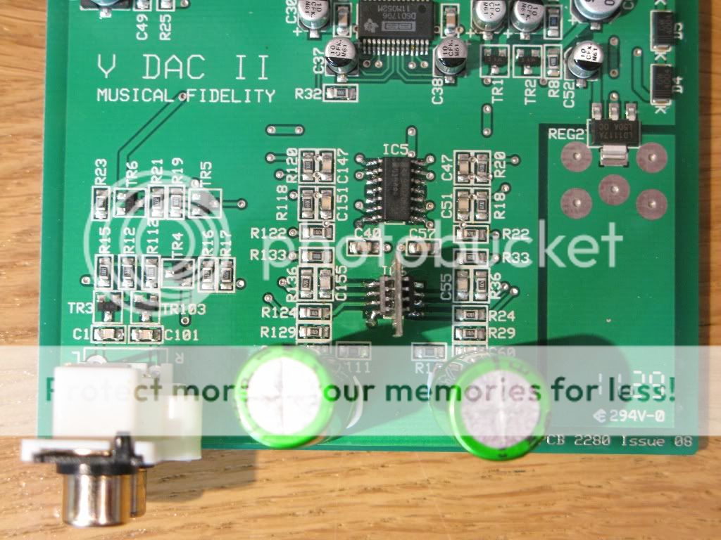
does someone care to kindly share the V-DACII schematics? I have lifted and broken the soldering pad of the output capacitor, so now I have to bring the signal to the capacitor from elsewhere. The multimeter shows that R133 and the remnant of the capacitor pad are in short-circuit, but without the schematics R133 seems a position too far behind, I am afraid I am jumping over some components in-between. Thank you in advance.
does someone care to kindly share the V-DACII schematics? I have lifted and broken the soldering pad of the output capacitor, so now I have to bring the signal to the capacitor from elsewhere. The multimeter shows that R133 and the remnant of the capacitor pad are in short-circuit, but without the schematics R133 seems a position too far behind, I am afraid I am jumping over some components in-between. Thank you in advance.
I don't have the schematics and couldn't find any on the internet (i.e. publicly available). Surely you could just trace the signal path with a DMM continuity tester? The PCB is a simple 2-sided design.
I burned-up quite a few pads in the end with all my tweeking and op-amp changing, but replaced traces with direct connections using Mundorf silver wire. I'm sure one was direct to the resistor you mention. Sound quality does not seem to have been affected in any way that is detrimental.
In fact, the V-psu2 has been added since and that made another improvement - instruments become more defined, with more musical character
Will
Will
Will,
thanks for your prompt response. I traced the continuity to the R133 and I pulled the signal to the output capacitor from there. I would still like to have that schematics in case someone has it. As for the PSU, shortly after buying my V-DACII I built the SuperTeddyReg which is great and which I warmly recommend as the upgrade for V-DAC. I opened one V-PSU and I must admit it is very basic and very noisy.
thanks for your prompt response. I traced the continuity to the R133 and I pulled the signal to the output capacitor from there. I would still like to have that schematics in case someone has it. As for the PSU, shortly after buying my V-DACII I built the SuperTeddyReg which is great and which I warmly recommend as the upgrade for V-DAC. I opened one V-PSU and I must admit it is very basic and very noisy.
- Status
- This old topic is closed. If you want to reopen this topic, contact a moderator using the "Report Post" button.
- Home
- Source & Line
- Digital Line Level
- Musical Fidelity V-DAC2 - opamp comaptibility