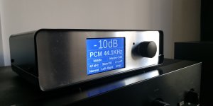
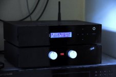
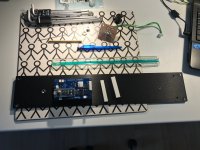
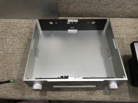
This is my newest project, but it is the first who get a housing. 🙂
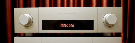
It is almost finished. I only have to polish the front plate and to make some measurements for the THD compensation coefficients: I hope to find a function between THD coeffs. and the digital volume values.
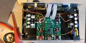
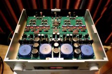
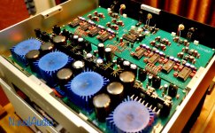
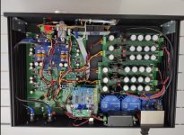
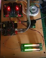
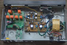
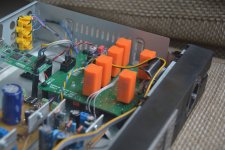
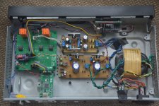
It is an USB DAC based on XMOS XUF208 and 2 x ES9018K2M.
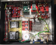
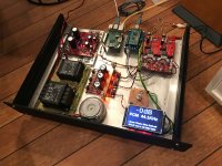
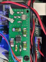
- The oscillator is adjustable SI549 and it feeds the clock for DAC chips, but also MCLK for XMOS via 3.1 (3 x I2S lines out from XMOS and 1 x MCLK line in to XMOS) 150MHz isolator, so the DAC works in synchronous mode.
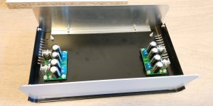
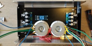
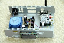
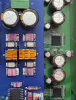
- There are two INDEL transformers 2X15vac 20VA plus 2x8vac coils each (I carefully made them by hand ). They are followed by 8 x LM317 pre-regulators, so all low noise (LT3042/45, ADM7150) LDOs get the right (minimum) input voltage in order to keep their temperature as low as possible.
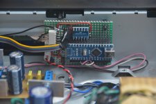
- The main controller is based on STM32F103 "blue-pill" - inspired by Dimitris project : www.dimdim.gr It is also isolated via 2 x I2C isolators: one for XMOS and the other for the DAC chips.
You can watch a short video here: YouTube
It is almost finished. I only have to polish the front plate and to make some measurements for the THD compensation coefficients: I hope to find a function between THD coeffs. and the digital volume values.
It is an USB DAC based on XMOS XUF208 and 2 x ES9018K2M.
- The oscillator is adjustable SI549 and it feeds the clock for DAC chips, but also MCLK for XMOS via 3.1 (3 x I2S lines out from XMOS and 1 x MCLK line in to XMOS) 150MHz isolator, so the DAC works in synchronous mode.
- There are two INDEL transformers 2X15vac 20VA plus 2x8vac coils each (I carefully made them by hand ). They are followed by 8 x LM317 pre-regulators, so all low noise (LT3042/45, ADM7150) LDOs get the right (minimum) input voltage in order to keep their temperature as low as possible.
- The main controller is based on STM32F103 "blue-pill" - inspired by Dimitris project : www.dimdim.gr It is also isolated via 2 x I2C isolators: one for XMOS and the other for the DAC chips.
You can watch a short video here: YouTube
Attachments


This is a very proper looking build! As custom as it gets! 😀
I love it when I see my designs inspiring fellow DIYers to build their own projects, some of which look considerably better than my own. 😛
I love it when I see my designs inspiring fellow DIYers to build their own projects, some of which look considerably better than my own. 😛
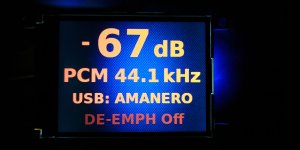
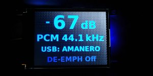
Using pictures stored in the flash memory chip gives better looking results than using text .h files. It is a little more work to be done (precise crop) for the text and background synchronization, but the effort deserves.
Attachments
DUAL AK4490
Hi...
This is DimDim's & freind's design
It was a long journey getting here, but i had good help from DimDim getting here.
It's finally done, and it's perfect as is for now.
Some pictures from build also included 🙂
Rgds; Jesper.
Hi...
This is DimDim's & freind's design
It was a long journey getting here, but i had good help from DimDim getting here.
It's finally done, and it's perfect as is for now.
Some pictures from build also included 🙂
Rgds; Jesper.
Attachments
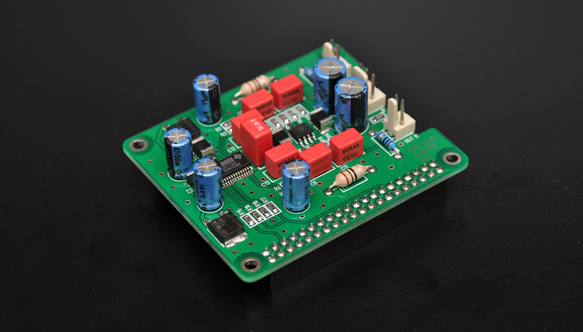
AD1865 NOS DAC for Raspberry Pi
Hi,
Here's my recent built.
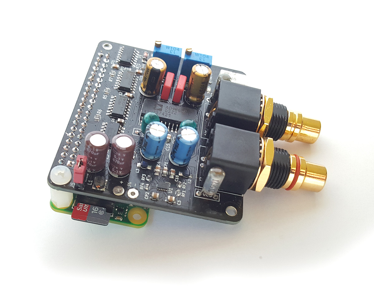
YouTube
and more info here:
DIY NOS AD1865 DAC for Raspberry Pi - Audiophile Diyer
🙂
Hi,
Here's my recent built.
YouTube
and more info here:
DIY NOS AD1865 DAC for Raspberry Pi - Audiophile Diyer
🙂

My latest DAC! PCM63 is my diy life 🙂
Attachments
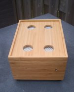
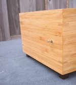
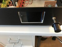
How did you fix the lid support blocks to the front and side panels?
Tapped blind holes? I can't see bolts on the outside. Only on the rear panel.
Looks great btw!
Tapped blind holes? I can't see bolts on the outside. Only on the rear panel.
Looks great btw!
How did you fix the lid support blocks to the front and side panels?
Tapped blind holes? I can't see bolts on the outside. Only on the rear panel.
Looks great btw!
Here is my Box 🙂
Attachments
My latest DAC! PCM63 is my diy life 🙂
Cool [emoji1591][emoji1303][emoji2]
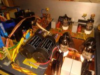
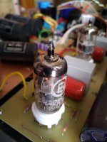
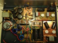
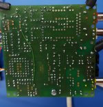
Priceless, man! Custom made PCBs - this is the pure diy spirit.Refresh old DAC with two PCM1702 and PMD100.
The I / V stage is with 6S4P. The output buffer is WCF with ECC88.
Amazing project, you are not living your diy life for nothing.My latest DAC! PCM63 is my diy life 🙂
My project
Link to the instructables project


Design files available too. Vote for the PCB design challenge in the bottom if you like it 🙂
Link to the instructables project
Design files available too. Vote for the PCB design challenge in the bottom if you like it 🙂
5 Kg of 5 years work
Finally, thanks to the quarantine, I've completed the exercises of:
Electronic design,
Components selection,
Arduino programming,
Mechanical design.
The main goal is scored: learned a lot (or at least something).
So this is DAC\preAmp:
Amanero USB, AK4137, Master clock: dual freq SI 80fs XO, 8xAK4490, MAS6116, all OPA1656 filters and attenuators. ADA4898-1 IVC, some Z-foil resistors, Sparkos Lab ±15V regulators, TPS7A4700 and LT3045 LDOs.
Digital - analog parts and stereo are galvanically isolated (at I²S);
Balanced only output;
8Vrms at 0dB, -60..+3dB range with mute;
4 digital filters and AKM sound control (does anybody know what's that?);
Less than 1.5mV offset at every output;
Nice 8mV 1Khz sinusoid (with 50Khz LPF);
Bluetooth to SPDIF with aptX;
5 colors touchscreen and remote control 🙂
Thanks a lot to Emisuke (http://emisukeaudio.sakura.ne.jp/) and Tachyonix ( TACHYONIX CORPORATION JAPAN) for the great kits which made this possible.
Attachments

@nemantree
Wow, that's impressive.
I love the Milling detail around the Display, very nice !!
I wish I was more adept at the Display/control aspects of this hobby, I would like a better control and Display of my selected Inputs.....fS for example.
Very nice.
P.
Wow, that's impressive.
I love the Milling detail around the Display, very nice !!
I wish I was more adept at the Display/control aspects of this hobby, I would like a better control and Display of my selected Inputs.....fS for example.
Very nice.
P.
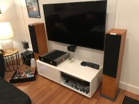
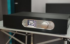
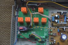
My new DDDAC 1794S for private use
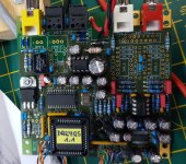
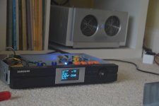
This is now my 5th DDDAC I built for my own use. It contains many ideas I collected, the tests I did, the tips I got here from the community, etc., etc.…
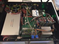
This is in short how it is built up:
4 Deck DDDAC, almost completely standard, but with Non Magnetic Silver Resistors for I/V
Roon Endpoint Raspberry PI3B with Ropieee
WaveIO USB input
SPDIF input
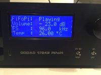
Ian Canada FiFoPi for reclocking the PI and the WaveIO I2S Signal
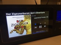
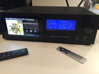
Ropieee based touch screen display as Roon Remote
RF Remote control for Roon and IR Apple thingy for the DAC, menu and volume control
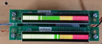
Sowter DDDAC special version TVC output with 18 taps and 36 Volume levels (added -20dB)
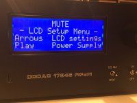
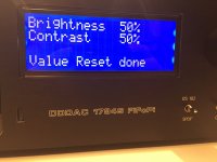
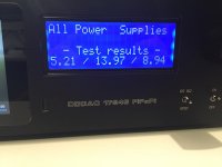
All Arduino MEGA2560 controlled for IR remote and front panel switches including test and setup menu
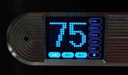
A separate Arduino UNO to measure the actual FS signal frequency and generate the sample frequency indication from the track in the display (like “44.1kHz” or “192kHz”).
Audio Creative “Magic Power Supply” (CLC type passive) for the DAC and the FiFoPi clocks
FiFoPi isolated clock section 3,3 V supply with a LT3045 LDOVR 78xx regulator
Input side of FiFoPi 4,3 Volt with a LT3045 LDOVR 78xx regulator – also feeding WaveIO I2S isolated output
LM317 9Volt Module for the Arduinos, FiFoPi input and the TVC control board
5V/4A SMPS to feed the raspberry PI3Bs, the display, the WaveIO and the selector relays board
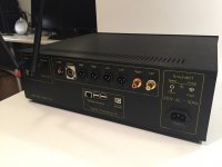
The DAC can be streamed to by Roon through Ethernet cable or through Wi-Fi ... That is why I removed the on board mini antennas of the two raspberry PI3B and extended the antenna in/output with a coax cable to the outside antennas. (I use two PI, one for the Display and one for the streaming)
The front and back are made by Schaefer in Berlin
The chassis and volume knob are from Modus HiFi in Italy
Next step: easy listening, enjoying the music and do compare tests with the 5 volt supply on the mainboard (I have a Bluetooth controlled A_B comparison board to do this, so any combination of two 5 volt regulators, VDO super regs etc., can be compared on the fly while music plays
Secondly, see if I can hear any SQ difference between Wi-Fi and Ethernet operation…
So far it was BIG fun again to build up this somewhat unusable DDDAC
This is now my 5th DDDAC I built for my own use. It contains many ideas I collected, the tests I did, the tips I got here from the community, etc., etc.…
This is in short how it is built up:
4 Deck DDDAC, almost completely standard, but with Non Magnetic Silver Resistors for I/V
Roon Endpoint Raspberry PI3B with Ropieee
WaveIO USB input
SPDIF input
Ian Canada FiFoPi for reclocking the PI and the WaveIO I2S Signal
Ropieee based touch screen display as Roon Remote
RF Remote control for Roon and IR Apple thingy for the DAC, menu and volume control
Sowter DDDAC special version TVC output with 18 taps and 36 Volume levels (added -20dB)
All Arduino MEGA2560 controlled for IR remote and front panel switches including test and setup menu
A separate Arduino UNO to measure the actual FS signal frequency and generate the sample frequency indication from the track in the display (like “44.1kHz” or “192kHz”).
Audio Creative “Magic Power Supply” (CLC type passive) for the DAC and the FiFoPi clocks
FiFoPi isolated clock section 3,3 V supply with a LT3045 LDOVR 78xx regulator
Input side of FiFoPi 4,3 Volt with a LT3045 LDOVR 78xx regulator – also feeding WaveIO I2S isolated output
LM317 9Volt Module for the Arduinos, FiFoPi input and the TVC control board
5V/4A SMPS to feed the raspberry PI3Bs, the display, the WaveIO and the selector relays board
The DAC can be streamed to by Roon through Ethernet cable or through Wi-Fi ... That is why I removed the on board mini antennas of the two raspberry PI3B and extended the antenna in/output with a coax cable to the outside antennas. (I use two PI, one for the Display and one for the streaming)
The front and back are made by Schaefer in Berlin
The chassis and volume knob are from Modus HiFi in Italy
Next step: easy listening, enjoying the music and do compare tests with the 5 volt supply on the mainboard (I have a Bluetooth controlled A_B comparison board to do this, so any combination of two 5 volt regulators, VDO super regs etc., can be compared on the fly while music plays
Secondly, see if I can hear any SQ difference between Wi-Fi and Ethernet operation…
So far it was BIG fun again to build up this somewhat unusable DDDAC
Attachments
-
 DDDAC1794S FiFoPi - 27.JPG340.3 KB · Views: 399
 -
 DDDAC1794S FiFoPi - 28.JPG413.8 KB · Views: 366
 -
 DDDAC1794S FiFoPi - 29.JPG450.8 KB · Views: 348
 -
 DDDAC1794S FiFoPi - 30.JPG342.4 KB · Views: 330
 -
 DDDAC1794S FiFoPi - 24.JPG325.4 KB · Views: 542
 -
 DDDAC1794S FiFoPi - 23.JPG687 KB · Views: 707
 -
 DDDAC1794S FiFoPi - 22.JPG600.3 KB · Views: 676
 -
 DDDAC1794S FiFoPi - 19.JPG455.6 KB · Views: 499
 -
 DDDAC1794S FiFoPi - 18.JPG365.9 KB · Views: 571
 -
 DDDAC1794S FiFoPi - 17.JPG300.9 KB · Views: 626
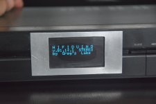
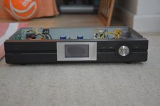
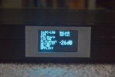
DA24QS DAC from beis completed
Just completed DAC from Uwe Beis in Germany. DA24QS - Audio Digital to Analog Converter 24 Bit / 192 kHz (Quad Speed). Quality PCB, easier to solder than I thought. (Service mounts are already done)
Had a broken track, I must have nicked it. Uwe was very quick in pointing me in the right direction. Sounds a lot punchier than the cheap one I was using. So well done Uwe.
Also using his AMBM - The Analog Meter Bridge Module Project to add some pretty lights to it.
Will house in a repurposed TEAC tuner reference housing together with Raspberry Pi based allo digione music server.
Attachments
Last edited:
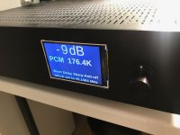
This is my ES9018.
It is more or less HiFIDuino. However given a slimmer chassis I could not fit 4x20LCD screen. I did not want to use 2x16LCD so I went for an OLED.
I thought it would be a nice Arduino exercise. And it looks better (not on photos - for some reason it is very hard to photograph them)
I inherited the DIYINHK board from a collegue at work. He has fried the DAC and the crystal, but was kind enough to desolder them. Otherwise the board was stuffed with nice components so it was worth trying to resurrect it.
I started with 4xLME49710 as IV converters and OPA134 as buffers.
Then I upgraded OPA134 to OP37 which I like quite a lot.
Meanwhile Burson Audio has offered to supply their discrete opamps for my DAC. I could not refuse. No strings attached. I needed to make a few pics and write what I think about them (good or bad). I waited a long time amid covid disruption but finally last month I got the V6 Classics from Burson. Initially I replaced the buffers with V6's. I liked the result very much.
More relaxed organic warm sound. The kind I like. The bonus: some residual sibilance present with OP37s was gone.
Then I replaced the IV converters. Yet more focus, more space, better separation of instruments. Yummy.
I am sold to Bursons to be honest.
I wonder how es9018 would sound with a discrete IV converters!
Attachments
-
 DSC_7121.JPG298.1 KB · Views: 412
 -
 DSC_7120.JPG379.8 KB · Views: 433
 -
 DSC_7119.JPG364 KB · Views: 412
 -
 DSC_7117.JPG311.3 KB · Views: 435
 -
 DSC_7115.JPG383.5 KB · Views: 429
 -
 DSC_7113.JPG313.7 KB · Views: 421
 -
 DSC_7112.JPG327.3 KB · Views: 459
 -
 DSC_7111a.jpg334.3 KB · Views: 475
 -
 DSC_7039a.jpg271.8 KB · Views: 465
 -
 DSC_7125.JPG346.5 KB · Views: 416
- Home
- Source & Line
- Digital Line Level
- DAC gallery