If you ever redesign the DAC to have I2S/USB input, I would love to have a board set. Always fancy in old-time NOS DAC. 🙂
It would love neater if you make the PSU board bigger to fit those 3 Talema transformers onboard.
It would love neater if you make the PSU board bigger to fit those 3 Talema transformers onboard.
Tks, maybe coming soon.If you ever redesign the DAC to have I2S/USB input, I would love to have a board set. Always fancy in old-time NOS DAC. 🙂
It would love neater if you make the PSU board bigger to fit those 3 Talema transformers onboard.
and I Always fancy in old-time NOS DAC, too
🙂
wacDAC
Second go at my DIY DAC
Low temp solder paste is your friend!
Some extra PCBs if anyone is interested
PCM 5122 based
Cheers

Second go at my DIY DAC
Low temp solder paste is your friend!
Some extra PCBs if anyone is interested
PCM 5122 based
Cheers
Second go at my DIY DAC
Low temp solder paste is your friend!
Some extra PCBs if anyone is interested
PCM 5122 based
Cheers
Nice work!
Third go! lol
Once you use the low temp solder paste your'e on your way!
Experimenting with different board colors and edges

Once you use the low temp solder paste your'e on your way!
Experimenting with different board colors and edges
Hey folks, I've decided to post photos of several D/A converters of mine here. I hope you will enjoy it 😉
First of all, moving-average 32x AD1865 DAC with no digital filter whatsoever (linear interpolation in hardware thanks to moving-average idea):
Another one is with one AD1864/AD1865 and an ASRC (AD1896) acting as digital filter upsampling to 210,9375 kHz. The analog filter is 10th order FDNR (frequency dependend negative resistor - Frequency dependent negative resistor - Wikipedia):
Several spinoffs were made of this idea resulting in discrette I/V stage with an active correction of input impedance with AD1864/AD1865, PCM1704 and TDA1541A:
THD of that D/A converter was well beyond three zeros after the dot:
PCM1704:
TDA1541A with low noise current source to create a bipolar output from it:
First of all, moving-average 32x AD1865 DAC with no digital filter whatsoever (linear interpolation in hardware thanks to moving-average idea):
An externally hosted image should be here but it was not working when we last tested it.
An externally hosted image should be here but it was not working when we last tested it.
An externally hosted image should be here but it was not working when we last tested it.
An externally hosted image should be here but it was not working when we last tested it.
An externally hosted image should be here but it was not working when we last tested it.
Another one is with one AD1864/AD1865 and an ASRC (AD1896) acting as digital filter upsampling to 210,9375 kHz. The analog filter is 10th order FDNR (frequency dependend negative resistor - Frequency dependent negative resistor - Wikipedia):
An externally hosted image should be here but it was not working when we last tested it.
Several spinoffs were made of this idea resulting in discrette I/V stage with an active correction of input impedance with AD1864/AD1865, PCM1704 and TDA1541A:
An externally hosted image should be here but it was not working when we last tested it.
THD of that D/A converter was well beyond three zeros after the dot:
An externally hosted image should be here but it was not working when we last tested it.
PCM1704:
An externally hosted image should be here but it was not working when we last tested it.
TDA1541A with low noise current source to create a bipolar output from it:
An externally hosted image should be here but it was not working when we last tested it.
An externally hosted image should be here but it was not working when we last tested it.
Last edited by a moderator:
Hey folks, I've decided to post photos of several D/A converters of mine here. I hope you will enjoy it 😉
But you have not said what they sound like!
Which do you prefer and why, compared to the others?
All of them do sound different and it is hard to pick one up since it all depends on your whole system, but if I had to choose one for mine I would go for moving-average with 32x AD1865. In fact, that is the one playing right now, however, the one with 1x AD1865 is quite good as well.
In general I do appreciate the sound from all of them, however, there is one which I didn't like much and that was PCM1704. I don't know what is about that chip, but I just don't like the way it sounds - it's not bad, but definitely worse than the others.
In general I do appreciate the sound from all of them, however, there is one which I didn't like much and that was PCM1704. I don't know what is about that chip, but I just don't like the way it sounds - it's not bad, but definitely worse than the others.
Lots of hours spent in PCB layout there, kudos.
I see you have some fairly complex active filters after your DAC, based on opamps. Have you tried LC (passive) filters? I ask because I tried a complex opamp-based elliptic filter after my DAC and didn't like the sound much. These days I only use passive filters - attached prototype 9th order LC filter I/V stage.
I see you have some fairly complex active filters after your DAC, based on opamps. Have you tried LC (passive) filters? I ask because I tried a complex opamp-based elliptic filter after my DAC and didn't like the sound much. These days I only use passive filters - attached prototype 9th order LC filter I/V stage.
Attachments

Lots of hours spent in PCB layout there, kudos.
I see you have some fairly complex active filters after your DAC, based on opamps. Have you tried LC (passive) filters? I ask because I tried a complex opamp-based elliptic filter after my DAC and didn't like the sound much. These days I only use passive filters - attached prototype 9th order LC filter I/V stage.
It's frequency dependent negative resistance and those opamps are not in the path of an audio signal. Take a look:
An externally hosted image should be here but it was not working when we last tested it.
Instead of NE5532 there are LM4562 though.
Last edited:
moving average filter
I suppose your x32 moving average filter is similar to the way used in DSD by Sygnalyst. AD1865 can't operate at high sampling freq like DSD topology. I guess 768kHz is the max. In such situation, the full addition of 32 outputs (every coefficient are 1) inevitably has high freq droop. How do you organize your 32 outputs for proper frequency response in the audio band? Are your coefficients not equal to 1?
I suppose your x32 moving average filter is similar to the way used in DSD by Sygnalyst. AD1865 can't operate at high sampling freq like DSD topology. I guess 768kHz is the max. In such situation, the full addition of 32 outputs (every coefficient are 1) inevitably has high freq droop. How do you organize your 32 outputs for proper frequency response in the audio band? Are your coefficients not equal to 1?
I suppose your x32 moving average filter is similar to the way used in DSD by Sygnalyst. AD1865 can't operate at high sampling freq like DSD topology. I guess 768kHz is the max. In such situation, the full addition of 32 outputs (every coefficient are 1) inevitably has high freq droop. How do you organize your 32 outputs for proper frequency response in the audio band? Are your coefficients not equal to 1?
maybe you can run a 1kHz squarewave (Fs44.1) through it and show the result?
I suppose your x32 moving average filter is similar to the way used in DSD by Sygnalyst. AD1865 can't operate at high sampling freq like DSD topology. I guess 768kHz is the max. In such situation, the full addition of 32 outputs (every coefficient are 1) inevitably has high freq droop. How do you organize your 32 outputs for proper frequency response in the audio band? Are your coefficients not equal to 1?
Moving-average is just a simple FIR filter, but the results are calculated within analog domain. In fact, its ability to filter and attenuate is quite poor in general. The idea is the same as within the following thread:
Building the ultimate NOS DAC using TDA1541A
It does exactly the same thing - linear interpolation in the analog domain.
Impulse response of that D/A converter looks like this:

1 kHz sinusoidal signal in a D/A converter with one AD1865 and NOS mode looks like this:

Having 32x AD1865 to interpolate that signal using linear interpolation (well, 16 to be precise since the other 16 are used to create inversion of the signal) looks like this:

4 kHz with 1x AD1865 in NOS mode:

4 kHz with 16x AD1865 and linear interpolation:

10 kHz with 1x AD1865 in NOS mode:

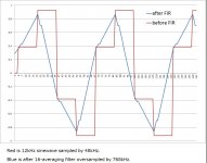
10 kHz with 16x AD1865 and linear interpolation:

The higher we get the ability to reconstruct the signal using such simple FIR is falling down quite heavily. It's expected and normal behavior.
However, after all - it does sound quite good. In fact, besides sounding good it does measure quite well since that kind of output swing from multiple AD1865 heavily decreases THD compared to only one AD1865:

There is not much to it. It's a really simple idea.
Last edited:
Thank you for your detailed explanation. It's very interesting and exciting! This is the first time to see 16 averaging by analog DAC and the performance.
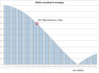
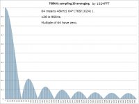
I did SIM from your screenshot of 10kHz with 16 averaging. I guess original data is sampled by 48kHz and upsampled to 768kHz to do analog interpolation.
The attached is 1024 length FFT. The second one is magnifying of the first. The third is 12kHz sinewave before and after the filter. It looks like your pic of 10kHz.🙂
Attachments
Cool! Indeed it is, I'm sorry I did not mention it. It's upsampled by a factor of 16 which means that for 48 kHz input it is running at 768 kHz on the output and for 192 kHz input it is running at... whooping 3.072 MHz 🙂
Cool! Indeed it is, I'm sorry I did not mention it. It's upsampled by a factor of 16 which means that for 48 kHz input it is running at 768 kHz on the output and for 192 kHz input it is running at... whooping 3.072 MHz 🙂
Linear linear interpolation is not upsampling. It simply changes the output waveform, prior to reconstruction, from zero-order hold to first-order hold. The true sample rate is unchanged but the distortion and high frequency attenuation is increased. This is easily seen in the photos in post #294.
Adding galvanic isolation to I2S adds massive jitter. Look at the ISO7640 data sheet. Added jitter is measured in NANO-seconds. And driving multiple DACs and shift registers with the same clock signal doesn't help, either.
It's just a matter of expression towards the question from xx3stkstm. There is no need to be cocky about it since I'm very well aware of how that D/A converter works.
How about you provide actual measurements of jitter? I performed several measurements including a J-Test in ARTA of this D/A converter and others and there is hardly anything to worry about. You do seem to scream a lot, but you have not much idea what is actually going on since reading datasheets won't get you anywhere if you don't know how real world works.
It is obvious for anyone who knows about filtering that this D/A doesn't do that very well. That was the whole point of this D/A converter - to try out how zero-order hold (NOS) and first-order hold (this DAC) differs from each other in terms of sound quality.
I agree with 3lite about jitter performance. I have measured jitter of optical SPDIF several times. Recovered clock from SPDIF receiver usually has 3 nanosecond jitter at max. It's easy to measure output jitter of DAC with jittery clock and with precise one. The clock to DAC is irrelevant to output jitter of DAC even if 3 nanosecond jitter exists. Jitter interference results in noise power of DAC output. Three nanosecond jitter is far less than 110dB THD+N, which is high-end performance.
What you need to measure is not the clock to DAC but the output of DAC. Noise power coming from the jittery clock is proportional to the DAC output frequency. The audio band frequency is very low(20kHz at max) while RF application is very high (more than 200MHz). In this situation, audio application inherently has less jitter oriented noise power by 80dB. That's why the output of DAC is not sensitive to jittery clock than a usual prospect many people have. That's my conclusion in the real world. The audio frequency is low.
What you need to measure is not the clock to DAC but the output of DAC. Noise power coming from the jittery clock is proportional to the DAC output frequency. The audio band frequency is very low(20kHz at max) while RF application is very high (more than 200MHz). In this situation, audio application inherently has less jitter oriented noise power by 80dB. That's why the output of DAC is not sensitive to jittery clock than a usual prospect many people have. That's my conclusion in the real world. The audio frequency is low.
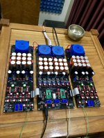
My new DAC
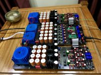
DAC chip: PCM-1704
Sampling/Filter: CS8414 and DF1704E
Digital Input: Spdif/ Optical and AES/EBU
Analog output: RCA and XLR
PSU with 4 Telama transformer
This ‘s DAC for CD transport! 🙂
DAC chip: PCM-1704
Sampling/Filter: CS8414 and DF1704E
Digital Input: Spdif/ Optical and AES/EBU
Analog output: RCA and XLR
PSU with 4 Telama transformer
This ‘s DAC for CD transport! 🙂
Attachments


- Home
- Source & Line
- Digital Line Level
- DAC gallery