Hi Bruno
The UCD180 has not by-passing caps after the regulation stage for the buffer opamp (that could avoid oscillations )
If i add one per rail , say BG 47uF//1nF , will it influence the sound ? Can it add resonance ? Or increase the slewrate ?
Alain
The UCD180 has not by-passing caps after the regulation stage for the buffer opamp (that could avoid oscillations )
If i add one per rail , say BG 47uF//1nF , will it influence the sound ? Can it add resonance ? Or increase the slewrate ?
Alain
Hi Alain,
There are capacitors in parallel with the 15V zeners. Not very near to the buffer opamp. When you upgrade to the AD8620 it is a good idee to put some extra decoupling capacitor.
But how this could influence the sound? I have to leave this question to Bruno......
Cheers,
Jan-Peter
www.hypex.nl
There are capacitors in parallel with the 15V zeners. Not very near to the buffer opamp. When you upgrade to the AD8620 it is a good idee to put some extra decoupling capacitor.
But how this could influence the sound? I have to leave this question to Bruno......
Cheers,
Jan-Peter
www.hypex.nl
i guess it's the same for all opamps. Depending on the regulator's quality it will make a difference in sound. I know that with an opa627 it's mandatory to use near-chip decoupling caps or it will sound like poop. I don't think bg's are necessary, though.
Some opamps are more sensitive to decoupling than others. When i was building a buffered gainclone i tested different opamps. The general outcome was that AD opamps are less sensitive to decoupling than TI opamps.
when using opamps i normally put something like 2,2uF (elco) bypassed with 0,1uF multilayer (ceramic) on each rail directly on the opamp pins. That does it for me.
I don't know about the 8620, though. Has anybody tried them yet? I'm having some difficulty finding 13v zeners at RS.
rha61 said:Hi Bruno
The UCD180 has not by-passing caps after the regulation stage for the buffer opamp (that could avoid oscillations )
If i add one per rail , say BG 47uF//1nF , will it influence the sound ? Can it add resonance ? Or increase the slewrate ?
Alain
Looking at JP's schematics it appears that there are 100nF ceramic caps present on the op amp rails (c41 c42). If you choose to use elcaps, remove the ceramics. Electrolytics are entirely sufficient decoupling (in this position), and adding ceramics in parallel is counteractive.
...and adding ceramics in parallel is counteractive.
forgive my ignorance but why is that?
National has a good application note about decoupling and the answer was that it's not obvious how you should choose parallel combinations.matjans said:
forgive my ignorance but why is that?
Maybe someone can dig up the application note?
In this regualtor case, the regulator may get unstable with too good decoupling. Compare the discussion about the Jung Regulator. This regulator may oscillate if the decoupling has too low losses. I have never experienced any problems with 78xx/79xx or LM3x7 regulators having "good" decoupling and also in parallel combinations.
Alain,
Indeed your version is revision 1, the changes to revision 2 is;
- new current protection. (current limiter)
- add overvoltage protection.
- add some extra decoupling capacitors for DIY modders 😉
Sonic spoken, there will be no difference!
Cheers,
Jan-Peter
www.hypex.nl
Indeed your version is revision 1, the changes to revision 2 is;
- new current protection. (current limiter)
- add overvoltage protection.
- add some extra decoupling capacitors for DIY modders 😉
Sonic spoken, there will be no difference!
Cheers,
Jan-Peter
www.hypex.nl
Re: ok to use 3 Bridges?
I would consider connecting some evenly distributed transformer turns over the outside of the present factory tape and connect them in out-of-phase series with the secondary center tap. 12 or 14 gauge electrical house wire could work well. Or you could use thinner wire and do a similar thing with two extra windings connected in out-of-phase series with each secondary. then, it may be better to make the turns bifilar; a good option might be 14 or 16 gauge zip cord (as in speaker wire). Add or remove turns to get closer to the voltage you want.
nickywicky said:I'm planning on getting 3 UCD400's when they become available and I'm sorting out the PSU in the meantime.
Found a really good deal on a 600VA 40-0-40 toroidal.
( 1/2 the price of a 500 va 35-0-35 if they even had
35vac ones! )
Problem is the no load voltage will be 61.5vdc. ( say 6% regulation of t/former at no load , voltage on New Zealand is always 4% higher than the rated 230 * 1.4 and -0.7 v for
the bridge), and the UCD400 is 60V max.
My question is, is it a reasonable to use a further 2 bridges to subtract 1.4Vdc to bring me pretty close to 60Vdc ?
I would consider connecting some evenly distributed transformer turns over the outside of the present factory tape and connect them in out-of-phase series with the secondary center tap. 12 or 14 gauge electrical house wire could work well. Or you could use thinner wire and do a similar thing with two extra windings connected in out-of-phase series with each secondary. then, it may be better to make the turns bifilar; a good option might be 14 or 16 gauge zip cord (as in speaker wire). Add or remove turns to get closer to the voltage you want.
Hi Jan-Peter,Jan-Peter said:Hans,
What you hear in your tweeter when you switch the amp on is a VERY small thick. Switching the amp off, doesn't create any noise........
When the customs has FINALLY gives our transformer free we will have a 160VA o-shape toroidel transformer.
Cheers,
Jan-Peter
www.hypex.nl
do you already know the pricing of these transformers? What voltage are they (... - 0 - ...) and what kind of advantage does the round shape give?
I'm thinking about using one UCD180 per woofer on a stereo dual 15" TCSound dipole as part of a 4-way (already have amps for the other 3-way main panel, namely AKSA) 🙂
Thanks,
Hans.
The reason why I generally avoid parallelling ceramic caps with something else (e.g. another ceramic cap!) is because circuit inductances are liable to form a resonant circuit together with the ceramic cap.
You can parallel a ceramic and an elcap if the ESR of the elcap is greater than sqrt(Lcircuit/Cceramic). BG caps have lowish ESR so this requirement is unlikely to be met.
Other tricks are to use another, smaller elcap as a "damper" or "snubber". Should you ever have wondered what the 22uF small elcaps are doing on the UcD rails, there you are.
Now, if you consider that elcaps have hardly more inductance than their own pins (contrary to popular belief), additional ceramics are unnecessary if the elcaps are small and close enough to the op amp you're trying to decouple. Their ESR and high capacitance will insure that they will never enter into any sort of resonance with other caps located elsewhere. Thus, consistently using only elcaps to decouple opamps is a no-brainer.
The point brought forward by Peranders is a different one.
Regulators are a control loop and the decoupling capacitors are actually a part of this. The highest performance circuits (such as jung etc) rely on this heavily. The ESR on elcaps placed across the regulator will act as a form of lead compensation, allowing better loop gain than would be available if the cap were perfect.
Jan-Peter said:
Hi Jan-Peter, Bruno and others,
I have revision one, I already saw that there are no decoupling caps after the regulators (well transistors like emitter followers with a zener defining the base voltage).
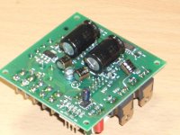
I have modified two of my UCD modules. Besides replacing and adding BG caps at different positions I also put decoupling after those regulators. I have put one 22uF 50V BG cap between the + rail and the - rail after the regulator, so not 2 caps to GND but one cap between the + and - rail. Besides that, I have added a 0.1uF BG-NX cap directly over pin 4 and 8 of the NE5532 opamp for decoupling close to the opamp. So I`m not decoupling to GND but between + and - rail. I think that should be OK and I think I read somewhere that that way of decoupling prevents GND noise to be transferred to the rails which could be beneficial? So I have done that mod but no listening yet.
I have also replaced the 22uF caps that are parrallel to the zener diodes with BG types. Replaced the 22uF coupling caps between NE5532 and UCD with 4.7uF BG-N types (this gives a cut-off frequency at 16Hz or so which is far lower than that of my speakers, so no problem). I did not remove the 22uF caps that are power supply decooupling caps close to the switching transistors. I wanted to replace them with 22uF BG caps, but there is not enough space. So I added 22uF BG caps in parallel on the underside of the PCB. I was also thinking of replacing the 470uF caps with 100uF BG caps (about the same size), but instead, I just added 100uF BG caps by mounting those also on the underside of the PCB.
See the attached picture for what I have done to the underside of the PCB.
If you have any comments/advice, please let me know.
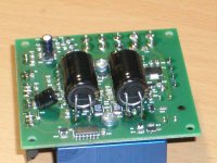
I`ll add another picture in a seperate post
Attachments
Hi,Hans L said:do you already know the pricing of these transformers?
JP already got scolded for having "done commerce" in this forum (we believe it was unintentional and in good faith). It's best to ask financial and other sales-related matters by private email. That saves him any further embarrassment.
Cheers,
Bruno
Depends on the applicationghemink said:I think that should be OK and I think I read somewhere that that way of decoupling prevents GND noise to be transferred to the rails which could be beneficial?
In single-ended (ground-referenced) circuits this can be a good thing, although it reduces the phase margin of the op amp.
In the UcD pre gain stage, ground is not used as a signal reference so the advantage of decoupling only across +/- is gone. The disadvantage (phase margin) remains, however.
Bruno Putzeys said:The reason why I generally avoid parallelling ceramic caps with something else (e.g. another ceramic cap!) is because circuit inductances are liable to form a resonant circuit together with the ceramic cap.
You can parallel a ceramic and an elcap if the ESR of the elcap is greater than sqrt(Lcircuit/Cceramic). BG caps have lowish ESR so this requirement is unlikely to be met.
Other tricks are to use another, smaller elcap as a "damper" or "snubber". Should you ever have wondered what the 22uF small elcaps are doing on the UcD rails, there you are.
Now, if you consider that elcaps have hardly more inductance than their own pins (contrary to popular belief), additional ceramics are unnecessary if the elcaps are small and close enough to the op amp you're trying to decouple. Their ESR and high capacitance will insure that they will never enter into any sort of resonance with other caps located elsewhere. Thus, consistently using only elcaps to decouple opamps is a no-brainer.
The point brought forward by Peranders is a different one.
Regulators are a control loop and the decoupling capacitors are actually a part of this. The highest performance circuits (such as jung etc) rely on this heavily. The ESR on elcaps placed across the regulator will act as a form of lead compensation, allowing better loop gain than would be available if the cap were perfect.
Hi Bruno,
Based on this statement in your above post:
You can parallel a ceramic and an elcap if the ESR of the elcap is greater than sqrt(Lcircuit/Cceramic). BG caps have lowish ESR so this requirement is unlikely to be met.
It seems like a bad idea to use BG caps in parallel with the 22uF normal elcaps that also have ceramic chip caps in parallel with them on the underside of the PCB. Is that true? If so, I`d better remove the BG caps at that point.
I had slight worries about the BG caps after the regulators (regulator stability) what do you think about that? Should I get rid off that 22uF cap and leave the 0.1uF that I placed directly over the opamp?
Best regards
Gertjan
Bruno Putzeys said:
Depends on the application
In single-ended (ground-referenced) circuits this can be a good thing, although it reduces the phase margin of the op amp.
In the UcD pre gain stage, ground is not used as a signal reference so the advantage of decoupling only across +/- is gone. The disadvantage (phase margin) remains, however.
Hi Bruno,
Thanks for the advice. I may reconsider this act and place a 22uF after the regulator between + rail and GND and - rail and GND. Using the GND connection that is also used by the zener. Then for the 0.1uF cap directly over the opamp. I don`t see any GND pin/pad in the direct neighborhood of the opamp so that is another reason why I placed that cap directly over pin 4 and 8.
Any advice appreciated.
Best regards
Gertjan
Well in any case if you want to place BGs at the position where the 22uF caps are in the power stage you would do good to remove the original caps first. If you're into placing components on the bottom side, the ideal place to have the "damper cap" is straight across the 100nF caps.ghemink said:
It seems like a bad idea to use BG caps in parallel with the 22uF normal elcaps that also have ceramic chip caps in parallel with them on the underside of the PCB. Is that true? If so, I`d better remove the BG caps at that point.
I had slight worries about the BG caps after the regulators (regulator stability) what do you think about that? Should I get rid off that 22uF cap and leave the 0.1uF that I placed directly over the opamp?
As for the op amp, make your life easy and have only two 22uF elcaps to ground.
Bruno Putzeys said:
Hi,
JP already got scolded for having "done commerce" in this forum (we believe it was unintentional and in good faith). It's best to ask financial and other sales-related matters by private email. That saves him any further embarrassment.
No problemo,
Hans.
- Home
- Amplifiers
- Class D
- UCD180 questions