I am struggling with ADAU1701 load level and sound quality tradeoff, in that it is extremely difficult to make a distinction between something caused by a high load level, or by something else in the design. Also, I can hear the difference in sound quality between near-100% load and 60-70% load, but not between somewhere around 70% (some 717 steps out of 1024) and 80% (819 steps).
Here is what I am using as an interim solution at 48kHz sampling rate:

It is based on the project on post #67 in this thread, with the dynamic bass boost parts removed to lessen the total number of instruction cycles and the load level. With the reduced number of speaker EQ filters from 5 to 4 and the All Pass filter Q set at 1.20, this project is using 612 steps (59.8%, according to compiler_output.txt).
It is based on the strategy:
1. Find the efficient set of filters using AutoEQ. I let it set over ten filters at the beginning, and gradually reduced the number in seeking the best compromise between frequency response and phase distortion. Currently I am using four peaking filters.
2. Reduce/adjust the boost level and Q Factor in each filter for a flatter phase response. I am using plus and minus 3dB and 3.0 Q as the limit now. If I use these limits in AutoEQ as the initial design criteria, the outcome becomes far apart from what I want. So I use the higher default settings for boost and Q in AutoEQ filter design, then reduce them manually when transferring the designed filters to a less resource intensive filter block than AutoEQ.
As a result, the delay introduced by the parametric EQ filter block is much less than 1 radian on the simulation. What you see beyond -1 radian on the lower right graph comes from the All Pass filter set at 8800Hz to counter the phase rise (reduction of delay as frequency goes up) on the lower left graph from 4000Hz to 11000Hz.
3. Adjust the set frequency of each filter higher or lower for the dips in filter phase response to coincide with the rises in speaker phase response.
4. Repeat step 2. and 3. until my ears agree with my eyes/brain on the shape of the simulated filter responses.
5. Measure the result with REW to make sure the effect of the filters appear on the measurement as intended.
I am not sure if the above approach is reasonable, or makes sense at all. But at least this set of filters sounds as good as, or better than the 48kHz no-filter project (on my system in my room) to my ears, depending on what part of sound characteristics I pay particular attention to while listening to the music. When my attitude is more "sit back and relax" to enjoy the music, I don't feel the difference.
A caution here is that I spent a lot of time/effort in finding the set of speakers I like for my room. So basically I like how they sound very much without a DSP. If you have more "I wish these speakers did more of this and less of that" items for the DSP to correct, the most appropriate/applicable approach could well be quite different.
`
Here is what I am using as an interim solution at 48kHz sampling rate:
It is based on the project on post #67 in this thread, with the dynamic bass boost parts removed to lessen the total number of instruction cycles and the load level. With the reduced number of speaker EQ filters from 5 to 4 and the All Pass filter Q set at 1.20, this project is using 612 steps (59.8%, according to compiler_output.txt).
It is based on the strategy:
1. Find the efficient set of filters using AutoEQ. I let it set over ten filters at the beginning, and gradually reduced the number in seeking the best compromise between frequency response and phase distortion. Currently I am using four peaking filters.
2. Reduce/adjust the boost level and Q Factor in each filter for a flatter phase response. I am using plus and minus 3dB and 3.0 Q as the limit now. If I use these limits in AutoEQ as the initial design criteria, the outcome becomes far apart from what I want. So I use the higher default settings for boost and Q in AutoEQ filter design, then reduce them manually when transferring the designed filters to a less resource intensive filter block than AutoEQ.
As a result, the delay introduced by the parametric EQ filter block is much less than 1 radian on the simulation. What you see beyond -1 radian on the lower right graph comes from the All Pass filter set at 8800Hz to counter the phase rise (reduction of delay as frequency goes up) on the lower left graph from 4000Hz to 11000Hz.
3. Adjust the set frequency of each filter higher or lower for the dips in filter phase response to coincide with the rises in speaker phase response.
4. Repeat step 2. and 3. until my ears agree with my eyes/brain on the shape of the simulated filter responses.
5. Measure the result with REW to make sure the effect of the filters appear on the measurement as intended.
I am not sure if the above approach is reasonable, or makes sense at all. But at least this set of filters sounds as good as, or better than the 48kHz no-filter project (on my system in my room) to my ears, depending on what part of sound characteristics I pay particular attention to while listening to the music. When my attitude is more "sit back and relax" to enjoy the music, I don't feel the difference.
A caution here is that I spent a lot of time/effort in finding the set of speakers I like for my room. So basically I like how they sound very much without a DSP. If you have more "I wish these speakers did more of this and less of that" items for the DSP to correct, the most appropriate/applicable approach could well be quite different.
`
Last edited:
As a sidebar, here is what I did to obtain the frequency response of my room.

Basic concept is when "Speaker Response" is subtracted from "Speaker Response + Room Response", Room Response is obtained as the residual.
"Speaker Response 1" is the normal measurement file measured at the listening position. Speaker Response 2 is the near field (50cm) measurement of the Right speaker. Speaker Response 3 is the nearfield measurement of the Left speaker.
"Add 1" (ADAU1701/Basic DSP/Arithmetic Operations/Signal Add) merges the left and right nearfield responses by adding them together. Probe2 and Probe3 are for side-by-side comparison of listening position graph and the merged signal graph in order to adjust the volume level of the merged signal down with "Gain2" so that the volume levels are as closely matched as possible.
The gain used for "Gain2" (ADAU1701/Basic DSP/Adjustable Gain/Single/Multiple Controls/No Slew (Standard)/Gain) in the capture, 0.640914, was obtained by a trial feeding of a single MLSSA file for the three Speaker Response blocks, and by trying to make the result of Probe1 as close as possible to zero.
The actual gain figure to be used here depends on the volume levels used in the measurements and the speaker-to-mic distance.
As there will be some residual noise (-100 to -120dB at best) in the result, you could play with modifying the above schematic using something like Value Cross Detection (ADAU1701/Basic DSP/Logic/Value Cross Detection) to remove it if you need to.
Unfortunately, Probe1 does not have the function to export the Room Response graph. But there is a convenient app called Web Plot Digitizer:
WebPlotDigitizer - Extract data from plots, images, and maps
that can be downloaded free to convert the captured image file of a graph into a data file.
The concept of Analog Computer may not be familiar to most people, but high-end oscilloscopes can do real-time arithmetic/logic operations on analog data. And when a digital computer is not fast enough (or becomes too large for the requirement), like when calculating the best course of evasive action upon detection of incoming missiles for a fighter plane, analog computers with opamp as the building block have been used for decades in the military (the programs are hard-wired and not changeable/programmable much).
As you can see in the above example, a DSP mimics a programmable analog computer, and it is a great toy to play with for me.
`
Yes and No.
You can use it if you are willing to use the amp with the top cover off. Or, you could open up two rectangular holes for the opamp to stick through. With some holes drilled on the bottom half of the case, this modification may create some airflow as an extra benefit.
There is about 33mm height room available above PCB, below case top, not including the height of a DIP8 socket.
Impressive (old school) work! I did the same but in Python. I found the one by SteveGnome posted by JoshuaB but it had some unnecessary external dependencies and it did not take input or output file names as command line arguments. So I rolled my own (it is written for Python 3 and works without any external dependencies on Mac, Linux and Windows).Here's a .cmd file named FRD2MLSSA for old school Windows users.
My Python version attached in zip file. I just drag-and-drop the files exported from REW on top of the Python-script and it happily convert them into a format SigmaStudio can read (the converted files also work with the super handy Speaker Response : MLSSA block found under "System" in SigmaStudio).
Attachments
Last edited:
@Psalmopoeus
I've come to notice one more limitation to use Burson V4. There are two small Elna Silmic II caps located very close to each of the opamp sockets (at least on the DAP1002 version I have). This small distance may not be enough to clear the bottom size of Burson V4/V6 as the height of the caps are taller than the height of the DIP8 socket. You could add one or two DIP8 sockets on top of the DIP8 socket on the PCB to clear the height of the caps if this turns out to be the case, although this will further increase the total height of the opamp.
@EmuMannen
Thank you very much for the post and sharing the script.
In the manual for the DAP2002 it says that the input sensitivity can be adjusted by changing 2 resistors. I want the DAP2002 to automatically turn on from standby to power on when a signal comes in on the input connectors (RCA). Can this be done?
Currently I always have to walk over and turn the whole thing on by pushing the volume knob. Since I use it for my backchannels in a 5.1 configuration, I would like it to stay on all the time OR only turn on when a signal is coming in......
Currently I always have to walk over and turn the whole thing on by pushing the volume knob. Since I use it for my backchannels in a 5.1 configuration, I would like it to stay on all the time OR only turn on when a signal is coming in......
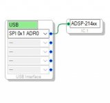
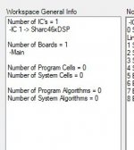
Dear Yiba, I have a 21489-based board, it works fine with the proprietary software, but when I go to sigmastudio, even though all seems correct (USBi green, active downloaded ...) I always obtain 0 cells and 0 algorithms in the link project tab. No errors in the error/output tab. Do you have suggestions to solve this problem?I stated previously that the linker and the compiler in Sigma Studio work very well and I haven't seen an error thrown by either of the two. I recently faced such an error, and it seems the error may be rooted in one of the under-developed areas of the IDE, the Graphical User Interface.

The above Linker fatal error on Sigma Studio Rev.4.6 was thrown when:
1. System sampling rate is set to 192kHz.
2. A double precision Nth order filter in Tree Toolbox was clicked and dragged over to the Schematic main pane.
3. When the mouse button was released to drop the filter in the Schematic area, it seemed the filter block was loaded into the memory, but the filter block GUI (icon) did not appear.
4. Link Compile Download (or Link Compile Connect) was done.
As the system sampling rate was 192kHz and there were other blocks in the Schematic, it is probable that the hardware limit was exceeded by adding the Nth order filter block.
Anyway, when the above situation happens and if you are not aware of the "filter was loaded into the memory" part of the above step #3, you will have no idea why this error occurred or how to solve the problem, as what you see on the screen does not tell you a clue about what's going on. (All the components and signal terminals in Schematic could appear connected despite what the error message tells you.)
My solution is to click and diagonally drag the empty area of Schematic where the "unsuccessfully dropped" block was when the mouse button was released at the end of the drag and drop operation. This will give you a rectangle of dotted lines covering the area, and selects any visible or invisible block in it. If you don't have any idea where on the Schematic this unsuccessful drop occurred, you may have to do try-and-error at several empty areas.
Once this is done successfully and see the rectangle, you can right-click and select Delete to remove the problematic block(s) from the memory. This trick can also be used when you have problems removing fragments of a block from Schematics after right-clicking its icon and selecting Delete, which happened on me trying to remove a 'T' connector that kept on leaving a fragment of the icon on the screen.
So the above 'LinkWind' (linker window) pic is worth keeping in mind for when you face a similar situation. Otherwise you could get stuck in the "unable to Link Compile Download" state for days.
`
Thanking you in advance
Antonello
Attachments

Hi YIBA, I was looking around for a low cost class D amp to use for some speakers in my shop and came across your thread.
What you have put in this thread is a great contribution to DiyAudio, thank you so much for all the details and explanation. Based on your information I'm going to order a SY-DAP1002 and do some of your mods. I probably won't do the DSP programming as I already have a miniDSP that I'm using for that. But the mods to improve sound quality are definitely a must. THANKS
gabo
I'm also getting stuck here. Tried SPI and resetting the device but no help. I got a TinySine TSA1701 and it seems to work fine, and I also tried TinySine's programmer. I have two 3E audio units so I don't think they're faulty. Any ideas?I have the 3e audio Dap 2002. I bought the USbi cable from 3e but have been unable to use the DSP. Whenever I click 'Compile Download' I get an error message saying 'Communication failure...check cable etc'. Unable to save any projects to my onboard DSP. I would love to see how you manage to use the DSP.
This thread made me buy one of these amps, and I'm very happy with it (using it for my experimental DML speakers, but that's quite another topic). Anyways, I was kinda miffed that the input and output stage in the Sigma Studio demonstration projects from 3e Audio were hidden, so I had a look and stumbled on a procedure to unhide them without having the passwords. Note that there was probably a good reason why these weren't exposed in the demo projects: don't mess with this unless you know what you're doing. Things will break. This is for educational purposes only.
Open one of the SY-DAP1002 demo projects in Sigma Studio version 4.7 (other versions may work or not, I haven't tried).
I've attached a zip file with an unlocked version of one of the demo projects, but please use the procedure above to check that the contents are indeed the unhidden version of the demonstration projects and not something that I made up. Trust, but verify.
Open one of the SY-DAP1002 demo projects in Sigma Studio version 4.7 (other versions may work or not, I haven't tried).
- Right click the "Input Stage" board, select "File -> Save Board" from the popup menu
- Save the board under an appropriate filename
- Repeat for the "Output Stage" board: right-click and save.
- Select the text windows with the notes that the boards are fixed and remove them. Also remove the one in the middle.
- Scroll down so the three boards are at the top of the window
- Right click the "Input Stage" board, and select "File -> Load Board..."
- Select the file that you saved the Input Stage to, and confirm that you wish to load this
- The "hidden" contents of the "Input Stage" board are now displayed in the Main window
- You may need to move the three boards up some more, so they are located above the all components (including the text labels) of the imported board
- Delete the now empty and unconnected "Input Stage" board from the Main tab
- Drag a new Hierarchy Board from the Tree Toolbox to the Main tab in its place, and name it "Input Stage"
- Select "View -> Zoom to fit" from the application's menu bar
- Select the entire imported block by dragging a rectangle with the mouse, leaving out the three boards. Make sure you don't miss out any of the text blocks. Cut the imported context using Ctrl-X
- Click on the "Input Stage" tab and paste using Ctrl-C. The contents are now again located in a board.
- Go back to the Main tab and repeat for the "Output Stage": Right-click and load the saved file.
- Confirm the import and delete the "Output Stage" board.
- Drag a new board to the Main tab and rename it to "Output Stage"
- Select and cut the imported contents using Ctrl-X.
- Click on the "Output Stage" tab and paste the imported contents to the board
- Go back to the Main tab and connect up the three boards
- Put the tabs in the correct order: move "Input Stage" to the left of "User EQ"
- Save the project.
I've attached a zip file with an unlocked version of one of the demo projects, but please use the procedure above to check that the contents are indeed the unhidden version of the demonstration projects and not something that I made up. Trust, but verify.
Attachments
The problem was buying DC/DC step down converters BL9352A. Chinese IC-s from Aliexpress from three
stores were fraudulent. From 4th I managed to buy working ones.
https://pl.aliexpress.com/item/1005008474923218.html
Regards
stores were fraudulent. From 4th I managed to buy working ones.
https://pl.aliexpress.com/item/1005008474923218.html
Regards
Last edited:
- Home
- Amplifiers
- Class D
- 3e Audio TPA3250D2 (SY-DAP1002) Mods & DSP Tuning