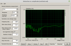
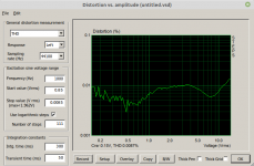
Surprise, surprise! The 2-layer PCB is slightly better in the region around 0.5V output voltage. So inspected the 4 layer and discovered that I had forgotten to solder the thermal pad of TPA3118. After soldering I got this result.
Now the 4-layer PCB comes close to the to the 2-layer version.
Now the 4-layer PCB comes close to the to the 2-layer version.
Attachments

Last edited:
So what are the conclusions?
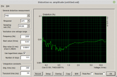
Moving from 2- to 4-layer PCB did not bring any significant difference concerning THD of TPA3118. Obviously the 2-layer PCB is "good enough" for TPA3118.
As found earlier, THD does not increase with dummy load indicating there is no room of improving the output inductors here.
Inside the interesting output range of 0.15~15V THD is below 0.01% - not bad at all.
At least moving to 4-layers eased pcb-design considerably and helped reduce size to 50x100mm.
I guess em-compliance improved as well but I do not have access to appropriate measurement setup, i.e. an emc-lab.
Last edited:
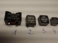
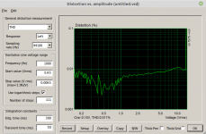
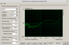
All inductors have a value of 10uH. THD vs output voltage at 1kHz, 24Vdc and 5Ohm dummy load are shown here
Attachments
Last edited:
While No1 &2 are close on par, the smaller cores show increasing distortion. This is to be expected as the smaller cores are driven into higher magnetic flux density than the bigger ones resulting in degraded linearity. Which confirms the experience that "size matters".
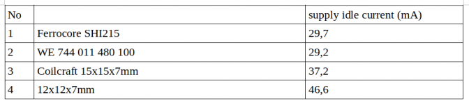
Another interesting result are the measured idle currents of the amp fitted with different inductors.
The smaller inductors cause higher idle currents than the bigger ones due to higher magnetic losses. This correlates to inductor related distortion.
So comparing inductors by simple measuring the amps idle current gives a quick overview for pre-selection.
Hint: As the measurement of total idle current includes the +-12V flybuck converter some 3~4mA are to be subtracted from the results.
Attachments
Last edited:
So what are the conclusions?
Moving from 2- to 4-layer PCB did not bring any significant difference concerning THD of TPA3118. Obviously the 2-layer PCB is "good enough" for TPA3118.
As found earlier, THD does not increase with dummy load indicating there is no room of improving the output inductors here.
Inside the interesting output range of 0.15~15V THD is below 0.01% - not bad at all.
At least moving to 4-layers eased pcb-design considerably and helped reduce size to 50x100mm.
I guess em-compliance improved as well but I do not have access to appropriate measurement setup, i.e. an emc-lab.
Sorry, I got a bit busy, totally lost the updates of this thread.
There are ways to at least measure relative EMI with just a regular probe "sniffer" on your scope. This way you can at least compare the two.
I am actually a little surprised about your 2-layer board results.
My experience is the complete opposite, that 4-layer board have much lower noise levels.
But a lot depends on how you choose the order of your layers as well as optimizing the PCB layout in general.
In the end that is still within the margins I suppose.
Have you ever done measurements between BD mode and SPW / hybrid mode ?
The total thickness of my 4-layer pcb was chosen to only 1mm for best heat sinking, which may have added to this effect. And I work the the old fashioned way without pre-heating the pcb which might help a lot. This is no big issue but may be a warning for the less experienced.
- Home
- Amplifiers
- Class D
- Class-D with TPA3118 - An Update after all these Years