Yes, you measure some 3V at the inputs independent of gain setting and supply voltage. This is kind of mystery to me, maybe these inputs internally are current summing nodes. So I would really wonder if the amp will work with an imposed DC-voltage at the inputs. And btw, I never saw any full DC application of any TPAxxxx class-D amp until now. I guess this could work driving the inputs with current sources instead of voltage sources.
Last edited:
The internal diagram shows the input is an inverting amp, it must be referenced to a fixed voltage. After all, it can't take input below the lowest supply voltage.
If I understand your question the right way - yes, it will oscillate above some critical point like any amp will do.
What I meant is, the TPA3118 is an oscillator driven class D amp. Give it too much feedback and the feedback signal will exceed the risetime of the internal ramp generator and then it will try to self-excite. Then you have an amp popping in and out of both operating modes and making all sorts of funny waveforms. The amp already has as much feedback as it can have without this happening. What have you done to keep the increased feedback from interfering with the ramp generator?
Mmm - my simulations are based on the state space average model, which works upto fpwm/2 if memory serves me. My attempts are to a good deal empirical, backed up by some real testings. As I mentioned earlier I do not like the idea of significantly reducing THD this way, as there was no real stable solution for me in sight until now. And I talk of stable without a snubber and without an ohmic output load.
On the other hand the differentiating PFFB proposed by me works for me rock solid for several years in reality. But this is me - maybe I have overseen something and somebody else finds a promising solution.
On the other hand the differentiating PFFB proposed by me works for me rock solid for several years in reality. But this is me - maybe I have overseen something and somebody else finds a promising solution.
Last edited:
The reason that TI doesn't provide a DC application seems pretty simple to me, because most of the world doesn't care 😀
caps are simple and cheap.
I have seen another discussion about PFFB with the TPA311x chips elsewhere, maybe even at TI's own support board? Can't remember.
Basically one can expect the same benefits and results as the TPA325x series.
Taking that as a starting point, you probably won't get much performance boost, maybe like 6dB or so.
It also does make the board design a little fiddly.
I agree, getting rid of the nasty impedance spike, is already a big win.
Have you ever tried to go to the highest gain setting and THAN applying PFFB?
Bruno Putzeys showed that you can get full control over the output filter with self-oscillating class D:
(PDF) Simple Self-Oscillating Class D Amplifier with Full Output Filter Control
However with oscillator based class D your unity gain point must be somewhere before the oscillator frequency. That means you don't have much space to change phase between your unity gain point and the filter frequency.
I had 2 ideas. Increasing the filter cap to 10uF and increasing the switching frequency to as high as it will go. But then you lose efficiency and output power.
With increased gain setting output noise and THD increases - consider in my type of PFFB there is no significant neg feedback in the audio band. So I stuck to the minimal gain setting for best audio quality.
@Keantoken. A possible explanation is that the differentiating PFFB yields some phase boost inside the feedback loop similar to type II/III frequency compensation shown for buck converters by late Dean Venable.
@Keantoken. A possible explanation is that the differentiating PFFB yields some phase boost inside the feedback loop similar to type II/III frequency compensation shown for buck converters by late Dean Venable.
Last edited:
The TPA3118 chip increases gain by decreasing loop gain, so if you add feedback afterward to get the same gain level you should have similar levels of distortion. The question is can you do so and get the same results as TI...
With increased gain setting output noise and THD increases - consider in my type of PFFB there is no significant neg feedback in the audio band. So I stuck to the minimal gain setting for best audio quality.
@Keantoken. A possible explanation is that the differentiating PFFB yields some phase boost inside the feedback loop similar to type II/III frequency compensation shown for buck converters by late Dean Venable.
Ah the THD as well, yeah it doesn't make much sense that way.
I could live with some additional noise in certain situations.
So lowering the gain even further wouldn't help/isn't possible?
since there is only 24V max available, 20dB is still quite a bit
This is what I have tried without satisfying results as you may read earlier in this thread. I measured THD improvements of about one magnitude - but stability was not was I was hoping for.
This is what I have tried without satisfying results as you may read earlier in this thread. I measured THD improvements of about one magnitude - but stability was not was I was hoping for.
Oh yes, you were mentioning it.
Although the zip didn't contain the spreadsheet with THD results, but just another LTSpice schematic 🙂
I think the problem is we don't know what the internal loop gain in the device looks like. That is what we need to modify to get what we want.
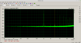
Meanwhile I did some THD-measurements with current PCB-version from 2021-03-03. My regular setup consists of an EMU-tracker soundcard, a 30dB-symmetric attenuator, 10R dummy load and a laptop. The DUT is powered by a lab power supply set to 15Vdc. The analyzing sw is ARTA running unter Linux Mint. These plots depict 1kHz THD at 10Vrms and 11Vrms output voltage reapectively.
Considering that 10Vrms correspond to more than +-14Vpeak this shows that hard clipping is very close to the supply rail voltage. I attribute this to the extra big output filter caps with 2u2. Earlier tests with TPA3255 showed that increasing output filter caps increases clipping level as well. Obviously this works with TPA3118 as well.
Considering that 10Vrms correspond to more than +-14Vpeak this shows that hard clipping is very close to the supply rail voltage. I attribute this to the extra big output filter caps with 2u2. Earlier tests with TPA3255 showed that increasing output filter caps increases clipping level as well. Obviously this works with TPA3118 as well.
Attachments
Last edited:
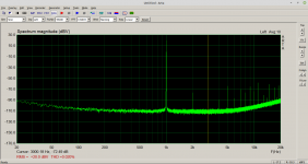
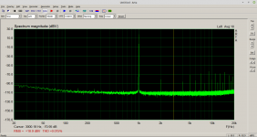
Measuring below clipping level at 9Vrms output gives these results with 5R0 / 10R dummy load respectively gives these results. Comparing
H1/H3 = 18.9dB-71dB = -89.9dB @5R0 with
H1/H3 = 19dB-71.8dB = -90.9dB @10R
shows no signifant difference with a load current changing by a factor 2.
This is indeed a surprising outcome that is contrary to common experience.
At the time I do not have any explanation for this.
As a side effect I conclude that the output filter inductors do not contribute significantly to distortion.
These are the same as in my TPA3255 boards and may be considered "oversized" for TPA3118.
Attachments
Last edited:
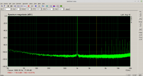
The same measurements with 3Vrms and 1Vrms output voltage feedeing 10R dummy give
H1/H3 = 0dBV - 89.4dBV = -89.4dBV @1V
H1/H3 = 10dBV-75.9dBV = -85.9dBV @3V
Not bad at all although nothing to call home about.
But hey, this is TPA3118 in a simple and stable setup🙂
H1/H3 = 0dBV - 89.4dBV = -89.4dBV @1V
H1/H3 = 10dBV-75.9dBV = -85.9dBV @3V
Not bad at all although nothing to call home about.
But hey, this is TPA3118 in a simple and stable setup🙂
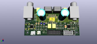
Meanwhile I revisited my current PCB design and plunged into 4-layer PCB the first time. So I can confirm this is a great step into better and easier design of such class-D modules. A batch of ten pcbs is now in production at JLCPCB. 😉
This is the kiCAD-3D preview:
This is the kiCAD-3D preview:
Attachments
Ha, great!
Looking good as well.
Since a PCB has two sides, what I personally like to do, is trying to put all SMD components on one side and all the THT or bigger parts (inductors) on the other side.
You will save a lot of space while still being able to let the board begin assembled easily.
Looking good as well.
Since a PCB has two sides, what I personally like to do, is trying to put all SMD components on one side and all the THT or bigger parts (inductors) on the other side.
You will save a lot of space while still being able to let the board begin assembled easily.
I did this as well, but with a class-d it is essential to achieve low-inductance power planes - i.e. wide copper areas instead of tracks - which can be done better with 4 layer.
Btw - I do not expect any sensational improvement of THD to take place with the 4 layer design, maybe due to better symmetry H2,H4 drop a bit, but H3,H5 will stay. Anyway a revision was due for several reasons, one of them being reduction of size from 62x110mm to 50 x 100mm.
Btw - I do not expect any sensational improvement of THD to take place with the 4 layer design, maybe due to better symmetry H2,H4 drop a bit, but H3,H5 will stay. Anyway a revision was due for several reasons, one of them being reduction of size from 62x110mm to 50 x 100mm.
Last edited:
- Home
- Amplifiers
- Class D
- Class-D with TPA3118 - An Update after all these Years