No, I don't expect that either.
Maybe a little bit of noise.
As long as you have proper local decoupling it's totally fine to use vias with powerplanes.
From the screen shot it seems that you can move all those passives over to the other side.
Or maybe even use the 3116 instead and move all higher parts over.
Just a suggestion
Maybe a little bit of noise.
As long as you have proper local decoupling it's totally fine to use vias with powerplanes.
From the screen shot it seems that you can move all those passives over to the other side.
Or maybe even use the 3116 instead and move all higher parts over.
Just a suggestion
Agreed. I did some test with continuous max power output for several minutes without overtemp shutdown, so TPA3116 and heatsink can be omitted imho. Some slight improvement is possible using TPA3128 instead of TPA3118.
Oh yes, I haven't really looked into that one, although I just only saw a slightly lower quiescent current?
Btw, I assume that this feedback technique would also work with something like a IRS2092 ?
Btw, I assume that this feedback technique would also work with something like a IRS2092 ?
Last edited:
Besides lower standby RDson is lower. I measured THD and this is on par and sometimes even better than TPA3118. I use the normal pwm-scheme. And no, none of its pwm schemes look compatible to the IRS which are free oscillating devices. With a similar price tag the TPA3128 may be preferrable choice to TPA3118.
90mOhm over 120mOhm, 25% less, is not that substantial, but meh, why not if it's basically the same price. 😀
They are pin compatible anyway.
I also noticed that it's possible to select a lower switching freq, 300kHz.
The lowest on the 3118 is 400kHz.
Usually this means better distortion in general, unless it's heavily optimized for higher freq switching. Most of these chip type amps aren't really optimized 😀
The lowest on the 3118 is 400kHz.
Usually this means better distortion in general, unless it's heavily optimized for higher freq switching. Most of these chip type amps aren't really optimized 😀
Normally I would expect a poor replica of TI app note, cost optimized by the bean counters. This is the best these small Asian companies can do to earn some money without too much engineering, and TI app notes are not bad at all. Which does not mean there was no room for improvement😉
Waiting for the next gen PCBs I did some full power continuous testing to verify the thermal behaviour. The signal level has been adjusted for light clipping, comparing TDA3118 with TPA3128 at 15V and 24V respectively. As formatted tables cannot be imported here the easy way I append a pdf document.
Attachments
Was continuous power done by a sine wave or pink noise?
It would be interesting to see a similar test at 400kHz
It would be interesting to see a similar test at 400kHz
I also noticed that it's possible to select a lower switching freq, 300kHz.
The lowest on the 3118 is 400kHz.
Usually this means better distortion in general, unless it's heavily optimized for higher freq switching. Most of these chip type amps aren't really optimized 😀
how is it possible to chose a 300kHz? using an external oscillator? For a minimal reduction of THD? Why make things more complicated?
how is it possible to chose a 300kHz? using an external oscillator? For a minimal reduction of THD? Why make things more complicated?
No, just look at the table in the datasheet.
They added an extra option at the "AM" pins.
Battery Operation Battery powered amps have been in my focus for decades. Starting in the eighties with a guitar amp based on a push-pull power MOSFET stage with 2xBUZ11 PowerMOSFETs and auto-transformer. This beast delivered about 30W into my 15inch driver from a car battery with a standby current of about 0.3 amps. During the nineties first attempts to build class-D followed with HIP4020 driver and discrete MOSFETs. Nowadays the TI-class-d-chips with analogue input are the way to go.
Battery operation requires some additional switchgear not necessary in mains powered equipment. Top on the list is a way to disconnect the battery automatically in emergency cases like battery undervoltage. Besides this it is a good idea to shut down power after a longer pause of audio signal - a strong indication that the user forgot to turn off the power switch. And power-up and power-down may require some specific sequencing to suppress popping noise that may originate from the power-stage but from the pre-amp as well.
These tasks are calling for some kind of microcontroller. As I am familiar with the Atmel range of 8-bitters I choosed the Attiny25/45/85 (the smallest one will do).
What we need is some kind of electronical switch controlled by the microcontroller. My first attempt was switching the pos supply rail be means of a p-channel power MOSFET driven by a a microcontroller port in conjunction with a level shifter. It should be noted that on power-up this power-MOSFET must charge the empty bulk caps, something like 1000uF or even more. Depending on the impedance of battery and bulk caps this may result in a current spike in the ballpark of 100 amps. Assuming a total impedance of 100 mOhms with 15V battery voltage a peak current of 150amps is possible. Switching within safe SOA specs is no brainer with some SO-8 p-MOS available from Infineon - alternative brand may do as well. This works for several years now without encountering any related problems.
Meanwhile I discovered a way to shut down the TPA3118 itself by tying down SDZ/fault pins. Power consumption dropped to about 100uA including leakage current of bulk caps. This eliminates the need of power switches keeping the bulk caps charged all the time. All in all a smarter solution.
It may be interesting to learn that I found a similar, undocumented way to shutdown TPA3251/3255 as well. Just removing the 12V-aux supply with a small p-MOS series switch does the trick.
Last edited:
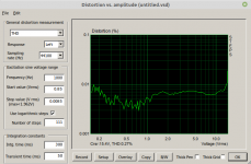
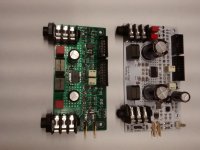
Some days ago the latest batch of PCBs arrived. So I populated my first 4-layer amp. Attached is a photograph of the previous 2-layer pcb (white) and the actual one (green). At first I measured 1khz THD at 5Ohms dummy load with 24Vdc supply.
Attachments
- Home
- Amplifiers
- Class D
- Class-D with TPA3118 - An Update after all these Years