Check what comes out of the LM25122. The LM2577 was the worst HF machine I have seen.
//
I did not notice anything too bad, but will double check, thanks.
But source of the audible noise is defenitely MA filters. During bring up I've used off board PSU.
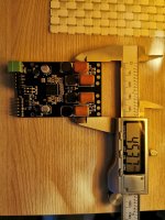
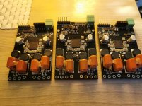
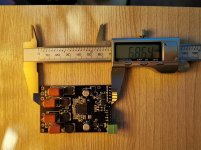
Here is my version of PCB for MA12070P. Nothing special, used Infineon's reference board design as a base. Added two Adum1250 to isolate I2C and MUTE and EN pins from microcontroller. Also added couple of buttons to switch I2C address and toggle between BTL and PBTL modes. And finally changed ferrite filters to LC filters.
https://www.infineon.com/dgdl/Infin...N.pdf?fileId=5546d46264a8de7e0164b359d78016f6
Also, what kind of power mode profile did you set during initialization of MA12070P? Based on datasheet the better one for LC is 3 (page 13)
https://www.infineon.com/dgdl/Infin...N.pdf?fileId=5546d46264a8de7e0164b761f2f261e4
I use Infineon recommendations about LC filters and didn't hear any noise. Did you hear it when you stop the music, is it hearable when amp is idle? Do you use any filter capacitor besides damping capacitor? 4 page (LC Filter)There are 3.3uH inductors in the output filters which are not necessary. And I don't know why, but when amplifier is enabled these are quite noisy! Maybe it's just bad choise of inductors. I've never heard any noise from inductors in TI based amplifiers.
https://www.infineon.com/dgdl/Infin...N.pdf?fileId=5546d46264a8de7e0164b359d78016f6
Also, what kind of power mode profile did you set during initialization of MA12070P? Based on datasheet the better one for LC is 3 (page 13)
https://www.infineon.com/dgdl/Infin...N.pdf?fileId=5546d46264a8de7e0164b761f2f261e4
Attachments
Hi! I have order Module d'amplificateur numerique de haute qualite HIFI MERUS MA12070 2X80W | AliExpress the i2s version ... I hope it will not be a hassle to configure ? whith usb board SA9227 interface usb dac conseil i2s pcm 384 kHz DSD 128 Numerique interface livraison gratuite | AliExpress
Have a nice day!
Have a nice day!
And this power supply :
Alimentation electrique 110 245V a cc 24V, 8a, 9a, 10a, module d'alimentation 220 | AliExpress
Alimentation electrique 110 245V a cc 24V, 8a, 9a, 10a, module d'alimentation 220 | AliExpress
Check what comes out of the LM25122. The LM2577 was the worst HF machine I have seen.
I see ~100mV p-p ripple under load. Not great, not terrible.
I use Infineon recommendations about LC filters and didn't hear any noise. Did you hear it when you stop the music, is it hearable when amp is idle? Do you use any filter capacitor besides damping capacitor? 4 page (LC Filter)
I found one mistake yesterday in my assembly, one cap value in the filter was wrong.
After fix the filter now is 3.3uH + 1uF, and RC is 2uF + 5.1 Ohm
When amp is idle the noise is much lower than under load. I actually can hear music coming from inductors when the amp is loaded by 6 Ohm resistors

Does not matter, I've tried all of them.Also, what kind of power mode profile did you set during initialization of MA12070P? Based on datasheet the better one for LC is 3 (page 13)
Here is waveform for filter in (or MA output, yellow) and filter out (blue).
There is some ringing, it should be possible to improve by ajusting filter parameters.
View attachment 910124
I hear that noise in idle, but it's very silent, as much as in other amps. Nothing noticeable.After fix the filter now is 3.3uH + 1uF, and RC is 2uF + 5.1 Ohm
When amp is idle the noise is much lower than under load. I actually can hear music coming from inductors when the amp is loaded by 6 Ohm resistors
Yes, I can hear that music come from inductors when resistors connected to the amp but in volume level 80-100%, so if I connect speakers to the amp I'll not hear that sound anyway.
Salut! J'ai commande Module d'amplificateur numerique de haute qualite HIFI MERUS MA12070 2X80W | AliExpress la version i2s ... J'espère que ce ne sera pas compliqué à configurer? avec carte usb interface SA9227 usb dac conseil i2s pcm 384 kHz DSD 128 Interface numérique livraison gratuite | AliExpress
Et cette alimentation:
Alimentation electrique 110 245V a cc 24V, 8a, 9a, 10a, module d'alimentation 220 | AliExpress
Nobody?
Et cette alimentation:
Alimentation electrique 110 245V a cc 24V, 8a, 9a, 10a, module d'alimentation 220 | AliExpress
Nobody?

Hi! I have order Module d'amplificateur numerique de haute qualite HIFI MERUS MA12070 2X80W | AliExpress the i2s version ... I hope it will not be a hassle to configure ? whith usb board SA9227 interface usb dac conseil i2s pcm 384 kHz DSD 128 Numerique interface livraison gratuite | AliExpress
Have a nice day!
You'll need an MCU to configure the amplifier chip via I2C. At least you need to choose right input format. For some strange reason merus chip by default will be configured for LJ format, but you need it to be configured for standard I2S.
You'll need an MCU to configure the amplifier chip via I2C. At least you need to choose right input format. For some strange reason merus chip by default will be configured for LJ format, but you need it to be configured for standard I2S.
Thanks a lot !!!! friend!!!
Not plug and play....
I'm going to tear my hair out again!!!

Thanks a lot !!!! friend!!!
Not plug and play....
I'm going to tear my hair out again!!!
Basically, yon'll need to implement initialization sequence on an MCU. Page 30 of MA12040 datasheet:
Make sure the all hardware pins are configured correctly: e.g. BTL, Slave Clock mode.
2) Keep the device in disable and mute: /ENABLE = 1; /MUTE = 0.
3) Bring up 5V VDD supply and PVDD supply (it does not matter if VDD or PVDD comes up first, provided that
the device is held in disable).
4) Wait for VDD and PVDD to be stable.
5) CLK must be present before enabling the amplifier.
6) Enable device: /ENABLE = 0.
7) Program applicable initialization to registers.
8) Unmute device: /MUTE = 1.
9) The device is now in normal operation state.

Salut! J'ai commande Module d'amplificateur numerique de haute qualite HIFI MERUS MA12070 2X80W | AliExpress la version i2s ... J'espère que ce ne sera pas compliqué à configurer? avec carte usb interface SA9227 usb dac conseil i2s pcm 384 kHz DSD 128 Interface numérique livraison gratuite | AliExpress
Et cette alimentation:
Alimentation electrique 110 245V a cc 24V, 8a, 9a, 10a, module d'alimentation 220 | AliExpress
Nobody?
Many of us do'nt read french so I think you should also add an english translation.
There is always googleTranslate
//
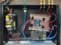
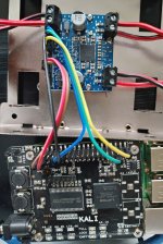
I have the ma12070P reference board. I'm trying to build a Raspberry Pi-based "sound server". The idea is to use a single 24V power supply. That directly powers the ma12070p board; it also powers a 5V buck converter for powering the RPI. For signaling, I'm directly connecting the I2C and I2S pins from the RPI GPIO header to the Infineon reference boards. See pictures.
In this config, I'm not getting any sound. I can communicate with the ma12070p board via I2C. I am using the "rpi-dac" overlay to push the I2S data. The Allo Kali is helpful, because the LED status indicators show me when a stream is active. Those do light up as expected when I play sounds. So I do believe I am creating an I2S stream.
The ma12070p has a number of I2S options available to configure via I2C; I believe I've tried them all (in particular, trying different versions of right-justified, which I think is more common). In my experience, if two devices don't agree on the I2S format, you should at least get noise. But I haven't been able to produce any sound.
My hunch is that I've overlooked something trivial, so just thought I'd see if anyone here notices anything obviously wrong. Thanks!
Attachments
In this config, I'm not getting any sound. I can communicate with the ma12070p board via I2C. I am using the "rpi-dac" overlay to push the I2S data. The Allo Kali is helpful, because the LED status indicators show me when a stream is active. Those do light up as expected when I play sounds. So I do believe I am creating an I2S stream.
The ma12070p has a number of I2S options available to configure via I2C; I believe I've tried them all (in particular, trying different versions of right-justified, which I think is more common). In my experience, if two devices don't agree on the I2S format, you should at least get noise. But I haven't been able to produce any sound.
My hunch is that I've overlooked something trivial, so just thought I'd see if anyone here notices anything obviously wrong. Thanks!
There are few wires missing: enb, muteb and mclk
See post 292. Are you sure you can communicate with the chip? Can you read status or volume registers?
Basically, yon'll need to implement initialization sequence on an MCU. Page 30 of MA12040 datasheet:
Hi!
Could it be compatible for reprogram the chip?
Thank you.

Programmateur automatique MCU STC 51, programmateur automatique, 3.3V 5V, universel/double tension, cable de telechargement USB vers TTL | AliExpress
There are few wires missing: enb, muteb and mclk
See post 292. Are you sure you can communicate with the chip? Can you read status or volume registers?
Thanks for the hint, I have some progress.
I deliberately didn't connect ENABLE and MUTE pins, as the board's reference manual says, "The board is shipped with a default configuration for automatic start-up". I also measured the voltage on those pins, ENABLE is 0, and MUTE is 5V (which are the settings for enabling playback and not muting). (However, I do think I'll ultimately connect those to the RPI GPIO pins for software control.)
The culprit seemed to be that MCLK pin. The RPI doesn't provide an I2S MCLK, and in reading about the ma12070p chip, I mistakenly thought it could be left unconnected. However, it looks like that pin on the reference PCB actually connects to pin 32/CLK of the amp IC, and the datasheet says this about that pin: "Clock input. Must be present before enabling the amplifier." Infineon actually makes an amp hat for the RPI Zero; looking at the docs for that (MERUS audio amp HAT ZW), they actually jumper MCLK and BCLK. So I used a paperclip to tie those two pins (i.e. pins 1 and 5 of the PAUDIO header on the reference board), and now it's playing music!
I've got volume control working via I2C as well, too. (For anyone else doing this, be careful with I2C addresses 0x35 and 0x36, they are used for both I2S config and volume processor/limiter config. I'll post code when this is in a more polished state.)
The only thing that's strange now is that there is an audible hiss and it sounds like it's coming from the PCB itself. I can't figure out what on the board could cause a hiss. If I physically jumper the MUTE pin to GND, then the hissing stops. When I pull the jumper, the hissing resumes, along with a pop.
First, where did you get those tiny terminal blocks? I soldered wires to those holes 'cause I couldn't find anything small enough.
I'm probably having a senior moment, but the MUTE and ENABLE pins of the chip are currently jumpered to VDD and GROUND, respectively. As I understand it, you would need to remove the jumpers to allow external control of those pins. Are you not creating a short when you ground the MUTE pin? If so, I wonder if the board is shutting down instead of muting.
Mike
- Home
- Amplifiers
- Class D
- Infineon MA12070 Class D