I'm actually not the guy who wants to talk about sounds of amplifiers as I usually only look on specs, but I think I know a little bit what you mean.
I had two Canton GLE490's as testspeakers and I also remember that the sound was a little bit... yeah I wouldn't call it aggressive.. but very direct..
However I was impressed by the serious amount of power which it was delivering into those (in comparison) huge speakers. This small device was really pushing them. And if you keep in mind, that it only uses PCB cooling without any additional cooling - that's pretty nice.
Last edited:
Well you can try it out.
I recently saw some newsletter that they have released two new boards:
One for Raspberry and one for Arduino MKRZERO.
KIT_ARDMKR_AMP_40W - Infineon Technologies
KIT_40W_AMP_HAT_ZW - Infineon Technologies
Both boards are powered by a 5V input USB-C connector.
They have an onboard integrated Boost converter from 5V to 20V (with max 500mA current out).
See schematic in the user-manual:
https://www.infineon.com/dgdl/Infin...N.pdf?fileId=5546d4626eab8fbf016eef8084096be6
Last edited:
By the way:
I'm already thinking since a little bit longer time to make a further hobbyproject with that MA12070P.
I recently managed on the ESP32 to get the I2S running bidirectionally.
I had in my mind something with 2* MA12070P, one ESP32 or so and then you can run DSP stuff on the ESP32 (e.g. IIR-filter) and manage a full 2.1 active controlled speaker system with WiFi-Control.
But not 100% sure yet about the details.
Anyone up for a collaboration?
The ESP32 with two I2S amplifiers would be a great system.
However, realizing the DSP and making it easily configurable is a real challenge. Or you would have to couple it to something like a TAS5805M/TAS5805M and control the built-in DSP via I2C commands. I saw the ESP32-Korvo-DU1906 already has this, but does not leverage the DSP of the TAS5805M as far as I can see.
Have you seen ESP-ADF? Great framework for wireless audio streaming.
The ESP32 could run a web-based GUI for easy configuration without having to download software or expensive programmers.
I am not too familiar with the ESP32 and related software. If you need help with schematics, layout and production, I am willing to help. You can reach me via DM.
For my own project I will personally use 2(3) my boards with MA12070P and then connect them to ADAU1452, I think it's esier to implement FIR filter by user in Sigma Studio and add digital volume control like this ADAU1452 for Digital Volume control - Q&A - SigmaDSP Processors and SigmaStudio Development Tool - EngineerZone
I am under the impression that generally, with class D amplifiers, you need (or at least want) some kind of filter on the output, to remove the high-frequency noise generated by the switching within the amp. So, I'm used to seeing boards for class D amplifiers sporting inductors that make up part of the LC filter circuit.
I don't see any inductors on that Audiophonics board @daniboun built with, nor on the eval board @maggusxy posted. However, I looked at the schematic for that eval board, and it appears they used ferrite beads on the outputs. Maybe the Audiophonics board does that too?
The TI tpa3110 datasheet, starting around page 15, talks about output filtering with ferrite beads and discussed when an actual LC filter may be necessary. Somewhere I seem to recall (almost certainly in the context of a TI class D amp) reading something that suggested using and LC filter when the speaker wire length exceeded some threshold.
So, two questions, really: (1) in general, what are the considerations for output filtering on class D amps? I know the switching frequency is well above the audible range. But the tpa3110 datasheet talked about how the IC's efficiency can be affected by the output filter. For commercial products, there are also EMI/EMF regulations that likely need to be met. But even for pure DIY, I'd prefer not to dump any EMI into my environment.
And (2) has anyone given any thought to the output filter design for these Infineon class D chips? I haven't spent much time with the datasheet. I'm more familiar with the TI class D chips, and you don't have to look very hard to see lots of discussions here about the output filter design and inductor choice for those chips.
Just for a fun plug-and-play toy, I was thinking about trying one of those Audiophonics boards (well, at least the identical-looking one available on AliExpress), but the lack of obvious output filter gave me pause. If there's no filter at all, then that implies it's pretty much certain to dump some EM noise into the environment. And if there's a simple ferrite bead filter, is that enough to keep it EM "clean" at higher power levels and longish speaker cables?
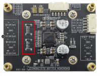
Sure, here they are (see attached image)I don't see any inductors on that Audiophonics board @daniboun built with, nor on the eval board @maggusxy posted. However, I looked at the schematic for that eval board, and it appears they used ferrite beads on the outputs. Maybe the Audiophonics board does that too?
So answering to both of your questions here is the Infineon PDFSo, two questions, really: (1) in general, what are the considerations for output filtering on class D amps? I know the switching frequency is well above the audible range. But the tpa3110 datasheet talked about how the IC's efficiency can be affected by the output filter. For commercial products, there are also EMI/EMF regulations that likely need to be met. But even for pure DIY, I'd prefer not to dump any EMI into my environment.
And (2) has anyone given any thought to the output filter design for these Infineon class D chips? I haven't spent much time with the datasheet. I'm more familiar with the TI class D chips, and you don't have to look very hard to see lots of discussions here about the output filter design and inductor choice for those chips.
https://www.infineon.com/dgdl/Infin...N.pdf?fileId=5546d46264a8de7e0164b359d78016f6
They recommend to use inductor 3.3uH for wires longer than 60cm.
Attachments
From what I understood is, that the radiated Emission on the multilevel Class-D is generelly not so high in comparison with other devices from e.g. TI.
On normal Class-D amplifiers, the output stage is bouncing the whole time e.g. with 300 kHz up-down between ground and v_supply with slewrates of < 100ns.
If you watch the output of the MA, you see in audio-idle condition almost no switching. It just stays at vdd/2.
And only with incoming signal modulating it starts switching between vdd, vdd/2 and gnd.
But the overall amount of switching is drastically reduced. Switching only when needed more or less.
And - I understood it not 100%, but due to multilevel-switching in H-bridge configuration, the virtually seen switching frequencies for the filters is also pretty higher.
Therefore, also with a real LC-filter, the needed inductance is quite lower (only 3.3uH). Other amplifiers need higher inductances between 10-33 uh. And of course you also get the inductors therefore cheeper for the needed current rating.
But for the target applications of this device which is I guess mostly Bluetooth-speakers or sound-bars, the cable-lengths is usually not longer then 80 cm or so. So a filterless-design might work out
You can also see this pretty well in this video, starting at 2:26
Next level of | audio performance with MERUS? | multilevel class d amplifiers | Infineon - YouTube
Or also here starting at 2:12
Infineon class D audio ? How it works @ CES 2019 - YouTube
Next level of | audio performance with MERUS? | multilevel class d amplifiers | Infineon - YouTube
Or also here starting at 2:12
Infineon class D audio ? How it works @ CES 2019 - YouTube
Last edited:
Here is the exmple of that design Customer experience with Infineon?s MERUS? class D audio solutions @CES 2019 - YouTubeYes that efficiency aspect is the most interesting one for me in terms of new applications. I'm interested to see how it fares running from a boost converter from say a USB 5V wall-wart or a 18650 cell.
@Onefabis - thank you, that answers all my questions (and more) in a very detailed way.
@maggusxy - also thank you, that is very helpful and interesting. So it sounds to me like, not only does their fancy switching scheme save power, but it also implicitly reduces the amount of EMI filtering that needs to be done.
Now that I've actually read some of the data sheet, I see it contains a fair amount of discussion on my questions!
On the board I have - which looks to based largely on Infineon's reference design - this supply (5V) is provided by a buck regulator (TI TPS62175) in a miniscule 10pin package. A look at the datasheet does not reveal how much output ripple can be expected. There is a post-filter prior to the Merus 5V supply pin (inductor L2) but without knowing the component values of the Ls and Cs its not possible to estimate how much reduction of the output ripple is going to occur.
Check out this document, the evaluation board user's guide. It contains a schematic of the evaluation board, complete with the 5V supply circuit. Probably a reasonable assumption that your board just copied this evaluation kit.
I think the ideal upgrade would be to install an LDO between the switcher and the amp chip
Just speculating here, but it seems one of the biggest selling points of this chip is the power efficiency. And a quick skim of the TPS62175 datasheet also talks a lot about power efficiency. So I'm guessing they chose this particular regulator to showcase power efficiency of a complete implementation.
The DS is quite involved, its tricky to understand all the ins and outs of 'Power modes' but the default is that the chip will automagically select the most suitable power mode depending on the signal level. It takes a CPU to override the automatic selection.
Hmm, thats a pity - would have been nice to be able to bolt it to one mode using strapping
Yeah, I was thinking the same thing. That serial interface is neat and annoying at the same time. Neat because it allows you to do on-the-fly tweaking of a lot of the chip's operating parameters. But annoying if you want to build something like a simple power amp where you just want to power it up and have it live in a fixed state.
Just thinking out loud here... I suspect there's some small/cheap microcontroller with I2C support. You could create a basic program for this chip, that does proper startup/shutdown sequencing, basic supervisory stuff, and also has some pins dedicated to physical jumpers that you could use to easily tweak some of the more high-level functions (e.g. PMP modes).
This reference board manual has sample code for quick connection and setup via I2C with arduino on Page 25:
https://www.infineon.com/dgdl/Infin...N.pdf?fileId=5546d46269bda8df0169da3392a743bd
https://www.infineon.com/dgdl/Infin...N.pdf?fileId=5546d46269bda8df0169da3392a743bd
Last edited:
Just thinking out loud here... I suspect there's some small/cheap microcontroller with I2C support. You could create a basic program for this chip, that does proper startup/shutdown sequencing, basic supervisory stuff, and also has some pins dedicated to physical jumpers that you could use to easily tweak some of the more high-level functions (e.g. PMP modes).
This reference board manual has sample code for quick connection and setup via I2C with arduino on Page 25:
https://www.infineon.com/dgdl/Infin...N.pdf?fileId=5546d46269bda8df0169da3392a743bd
If you are a Squeezebox fan like me, this reference board works well connected to a Raspberry Pi running piCorePlayer. Now, if they could add support for this amp in Squeezelite-ESP32
This reference board manual has sample code for quick connection and setup via I2C with arduino on Page 25:
https://www.infineon.com/dgdl/Infin...N.pdf?fileId=5546d46269bda8df0169da3392a743bd
I have purchased a MA12070P reference board and learned I need to configure it for I2s. I don't use Arduino and haven't used I2C before.
What is the easiest way (for me) of getting the MA12070P board to recognise I2S?
if I bought the EVAL board, can I piggyback the reference board somehow, to program the registers?
Thanks!
Mike
The easiest way, if you'd like to use it in standalone mode, without PC, simply buy chineeseI have purchased a MA12070P reference board and learned I need to configure it for I2s. I don't use Arduino and haven't used I2C before.
What is the easiest way (for me) of getting the MA12070P board to recognise I2S?
if I bought the EVAL board, can I piggyback the reference board somehow, to program the registers?
Thanks!
Mike
Arduino nano (4-5$). It also use A4 pin as SDA and A5 pin as SCL and run the code I mentioned above (with slight modification), I can assist you with the code if you'll have troubles with it. Luckily, MA12070P can accept 5v logic from arduino nano, so you'll not burn the chip.
What is the easiest way (for me) of getting the MA12070P board to recognise I2S?
The easiest way for me turned out not to feed it I2S, rather its default format (left-justified). I was able to change format because my I2S is created by an AK4113 SPDIF receiver chip and left-justified is one of the supported formats. I'd guess other SPDIF receiver chips support it too. I just had to twiddle one pin from logic 0 to logic 1. But you might have 'inviolable' I2S in which case you'll need to go down the I2C route.
- Home
- Amplifiers
- Class D
- Infineon MA12070 Class D