If you send your requirements I can export a complete header file for you.
My requirements are:Process Flow 8 (Housekeeping, 2.0),up to 192kHz,32bit audio process,Hybrid Modulation,BTL Mode(2.0 Channel), PWM frequency set to 768 kHz and Class D bandwidth set to 175kHz,PVDD Tracking / Thermal Foldback disable,others are set by default.
Where did you get it from?
I get the header file from a post on e2e audio forum
Question of TAS5825 Audio Format Support in PPC3
Although it was not what I really wanted, it still helped me a lot.
By the way,I found some necessary registers in the TAS5805M datasheet,which is exactly the same as the TAS5825M.
Best regards,
Firerunning
Here is a header file dump of the Housekeeping flow that is already:
-Set to 32 bit data
-Set to hybrid modulation, Fsw=768khz and bandwith=175khz
The header file contains example code on how to write the settings to the device in C. Change to .h instead of .txt before use.
I used this way of setting the DSP on a custom PCB with atmel processor. In my case there was a small catch:
The array is big, so it needs to be placed in flash by adding 'const PROGMEM' before the arrayname. After that if you want to read the contents back you have to use 'pgm_read_byte_near'.
I don't know the specifics for your micro, you have to figure that part out yourself.
Attachments
I am a bit concerned by the power dissipation on the PCB. Would it make sense to use this circuit in dual mono, using 2 chips in PBTL mode (even for 8 ohm loads) in order to spread the heat dissipation on 2 chips?
@lutkeveld
Thank you for the header file provided. I tried to configure the amplifier based on the header but failed. After I set it to BD Mode and deleted the DSP coeffs,the amplifier work again. I found that the coeffs can not be written in. This is a mystery.
Thank you for the header file provided. I tried to configure the amplifier based on the header but failed. After I set it to BD Mode and deleted the DSP coeffs,the amplifier work again. I found that the coeffs can not be written in. This is a mystery.
@Aurel32 I would not be too concerned when you are playing music. If you listen to sinewaves it might be troublesome. PBTL would be better for heat dissipation but doubles idle current, component cost and board space.
@firerunning Please confirm that the chip acknowledges all commands and writes the whole array. It should work, I suspect you have something wrong in your I2C write functions.
@firerunning Please confirm that the chip acknowledges all commands and writes the whole array. It should work, I suspect you have something wrong in your I2C write functions.
@lutkeveld
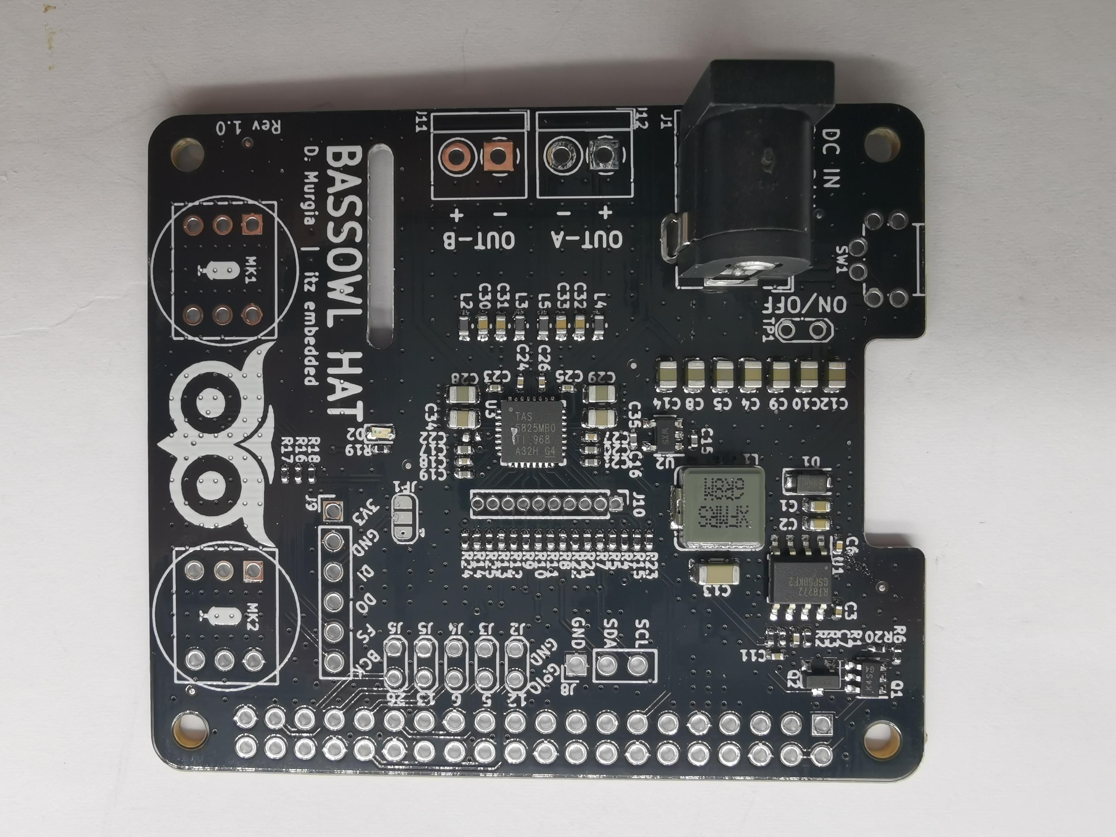
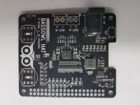
Thanks a lot for the feedback, this was enough to decide myself to build an amplifier based on this chip. I have chosen to build it as a form of an Raspberry Pi Hat:

So far I have only tested it with a 12V power supply, I have already ordered a 24V power supply with sufficient output power. It works and sounds great, it's incredible how such a small chip can output so much power with so good quality. It's a big change from my DAC + preamp + Mosquito amplifier in 19" enclosures for basically the same performances.
The TAS5825M is used with a 10µH/680nF output filter. I used the same Murata inductors as in the EVM. The PVDD power supply is bypassed with 2x680µF + 2x10µF ceramic + 100nF ceramic per channel. It uses a 2 layer PCB board, and the bottom layer almost consists in a ground plane, which I hope will be sufficient for power dissipation. I'll have to wait for the 24V power supply to test that. The 3 GPIO outputs are connected to 3 LEDs, the TAS5825M can be configured to display various information (fault, warning, automute, etc.).
I am used to solder chips with an exposed pad and with leads using a reflow station and flux but without stencil. I have applied the same technique for the TAS5825M, basically as shown there: YouTube. It was however less easy than expected, the surface tension was not so important as with a chip with leads, and thus I had to align it perfectly during the reflow. Nevertheless I have been able to solder it correctly.
The board also contains a 5V 3A DC/DC converter based on a LMR33630 chip to backpower the Raspberry Pi. It also features an LTC4365 DC input protection to protect the board from wrong polarity (as it can happen with this style of jack), under or over voltage. Mouser ran out of stock between the moment I passed my order and it got prepared, so I have not solder that part yet. I'll do that when I receive it in the next days. Finally the board also hosts a 24LC32 EEPROM to meet the Raspberry Pi HAT specification.
I have designed the board using Kicad. In the next weeks, I plan to change a few minor issues I noticed on the current board (like silkscreen, via diameter) and release the design in an opensource license.
On the software side, as an amateur I do not have access to PPC3. I therefore used the Housekeeping.txt sequence from @lutkeveld to initialize the TAS5825M. The chip is capable of way more things, I'll look at that later. Right now I am using a small Python code using py-smbus, but I plan to write a proper kernel driver at some point.
Thanks a lot for the feedback, this was enough to decide myself to build an amplifier based on this chip. I have chosen to build it as a form of an Raspberry Pi Hat:
So far I have only tested it with a 12V power supply, I have already ordered a 24V power supply with sufficient output power. It works and sounds great, it's incredible how such a small chip can output so much power with so good quality. It's a big change from my DAC + preamp + Mosquito amplifier in 19" enclosures for basically the same performances.
The TAS5825M is used with a 10µH/680nF output filter. I used the same Murata inductors as in the EVM. The PVDD power supply is bypassed with 2x680µF + 2x10µF ceramic + 100nF ceramic per channel. It uses a 2 layer PCB board, and the bottom layer almost consists in a ground plane, which I hope will be sufficient for power dissipation. I'll have to wait for the 24V power supply to test that. The 3 GPIO outputs are connected to 3 LEDs, the TAS5825M can be configured to display various information (fault, warning, automute, etc.).
I am used to solder chips with an exposed pad and with leads using a reflow station and flux but without stencil. I have applied the same technique for the TAS5825M, basically as shown there: YouTube. It was however less easy than expected, the surface tension was not so important as with a chip with leads, and thus I had to align it perfectly during the reflow. Nevertheless I have been able to solder it correctly.
The board also contains a 5V 3A DC/DC converter based on a LMR33630 chip to backpower the Raspberry Pi. It also features an LTC4365 DC input protection to protect the board from wrong polarity (as it can happen with this style of jack), under or over voltage. Mouser ran out of stock between the moment I passed my order and it got prepared, so I have not solder that part yet. I'll do that when I receive it in the next days. Finally the board also hosts a 24LC32 EEPROM to meet the Raspberry Pi HAT specification.
I have designed the board using Kicad. In the next weeks, I plan to change a few minor issues I noticed on the current board (like silkscreen, via diameter) and release the design in an opensource license.
On the software side, as an amateur I do not have access to PPC3. I therefore used the Housekeeping.txt sequence from @lutkeveld to initialize the TAS5825M. The chip is capable of way more things, I'll look at that later. Right now I am using a small Python code using py-smbus, but I plan to write a proper kernel driver at some point.
Board looks great! I was also thinking about a hat PCB, but you beat me to it. Its a shame that TI's software is not more open.
Reverse polarity protection can also be done with a simple P-channel mosfet:
Reverse voltage protection with a P-FET | Hackaday
Reverse polarity protection can also be done with a simple P-channel mosfet:
Reverse voltage protection with a P-FET | Hackaday
Reverse polarity protection can also be done with a simple P-channel mosfet:
Reverse voltage protection with a P-FET | Hackaday
I agree, that said the circuit there is doing more than reverse polarity protection, it also disconnects the load if the voltage is too high (I set the limit at 28V) or too low. Powering it with a too low voltage (that could be due to current protection) will leave the Raspberry Pi in a bad state and can corrupt the SD card.
Thanks for the feedback. I wonder if it is possible to add a small heatsink over the chip. It's very thin, so it might prevent placing decoupling capacitor very close to the chip.
It's nice that you have been able to reverse engineer the register map as the TI software is not available to hobbyists (they want a real company name). Is it the same DSP that can be found for example in the PCM5242?
It is recommended to add a small heatsink on top of the TAS5825M especially when using the PBTL mode to drive the fullrange speaker or small-subwoofer. I did that, it turns out to be working better than without heatsink.
@lutkeveld
Thanks a lot for the feedback, this was enough to decide myself to build an amplifier based on this chip. I have chosen to build it as a form of an Raspberry Pi Hat:
View attachment 751172
So far I have only tested it with a 12V power supply, I have already ordered a 24V power supply with sufficient output power. It works and sounds great, it's incredible how such a small chip can output so much power with so good quality. It's a big change from my DAC + preamp + Mosquito amplifier in 19" enclosures for basically the same performances.
The TAS5825M is used with a 10µH/680nF output filter. I used the same Murata inductors as in the EVM. The PVDD power supply is bypassed with 2x680µF + 2x10µF ceramic + 100nF ceramic per channel. It uses a 2 layer PCB board, and the bottom layer almost consists in a ground plane, which I hope will be sufficient for power dissipation. I'll have to wait for the 24V power supply to test that. The 3 GPIO outputs are connected to 3 LEDs, the TAS5825M can be configured to display various information (fault, warning, automute, etc.).
I am used to solder chips with an exposed pad and with leads using a reflow station and flux but without stencil. I have applied the same technique for the TAS5825M, basically as shown there: YouTube. It was however less easy than expected, the surface tension was not so important as with a chip with leads, and thus I had to align it perfectly during the reflow. Nevertheless I have been able to solder it correctly.
The board also contains a 5V 3A DC/DC converter based on a LMR33630 chip to backpower the Raspberry Pi. It also features an LTC4365 DC input protection to protect the board from wrong polarity (as it can happen with this style of jack), under or over voltage. Mouser ran out of stock between the moment I passed my order and it got prepared, so I have not solder that part yet. I'll do that when I receive it in the next days. Finally the board also hosts a 24LC32 EEPROM to meet the Raspberry Pi HAT specification.
I have designed the board using Kicad. In the next weeks, I plan to change a few minor issues I noticed on the current board (like silkscreen, via diameter) and release the design in an opensource license.
On the software side, as an amateur I do not have access to PPC3. I therefore used the Housekeeping.txt sequence from @lutkeveld to initialize the TAS5825M. The chip is capable of way more things, I'll look at that later. Right now I am using a small Python code using py-smbus, but I plan to write a proper kernel driver at some point.
That's a great move! By the way, if you need one to play around, send me your address. I send one for free to you to play around. I have the PPC3 and PPC2. I have done the demo board with ADAU1701 + TAS5805(PBTL) for testing purpose.
I have designed the board using Kicad. In the next weeks, I plan to change a few minor issues I noticed on the current board (like silkscreen, via diameter) and release the design in an opensource license.
It is already way more than a few weeks. I haven't finished the software part of this project (the Linux kernel module) as things basically work for me and I haven't find the time and motivation to write an upstreamable kernel module yet. I'll try to get it done at some point, but it the meantime I have decided to publish what I have so far as it can be useful to others:
electronics/rpi-amp.git - 2 x 30 W RMS Amplifier for Raspberry Pi
Compared the board I have built, I have only slightly changed the schematic and the PCB: changed some of the devices from the KiCad library ones now that my PRs have been accepted, value changes for the LED resistor, via diameter changes and small silkscreen change.
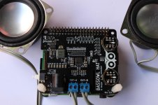
Hi aurel32,
just today I received pictures of a project I did recently, very similar to the PCB you designed. If I knew in advance it was already done, I would have saved lot of time 😀
I'll give a try to your driver, hopefully it will work for my board too.
just today I received pictures of a project I did recently, very similar to the PCB you designed. If I knew in advance it was already done, I would have saved lot of time 😀
I'll give a try to your driver, hopefully it will work for my board too.
Attachments
I forgot to mention, maybe this can be helpful for you as well
http://e2e.ti.com/support/audio/f/6/p/722027/2699754#2699754?jktype=e2e
regards
Dario
http://e2e.ti.com/support/audio/f/6/p/722027/2699754#2699754?jktype=e2e
regards
Dario
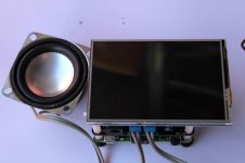
PCBs arrived from China, i'm very happy about the final result!
My plan was to verify the functionality of all blocks, this I did so far
- I2S microphones
- Back-powering of RPi
- 3.5" SPI screen
- I2C reading/writing with i2cget/i2cset
- I2S signals on the test-points, loading a generic I2S dt-overlay
Next step is to play audio. My idea was the following, already tested with other amplifiers:
- Load a generic I2S dt-overlay to provide 48kHz/16bit audio stream, always on
- Start audio playback, to activate I2S signals
- Launch a script with a sequence of I2C writings, bare minimum for playing audio (even bypassing DSP)
I'm missing the last part. I tried to look on the old threads, the attachment is this one is the closest example of what I need, but I can't find where PAGE and BOOK are defined.
I want to finalize the HW bringup before trying to implement a proper linux driver with help from some friends.
Attachments
All the registers defined in the datasheet are on book 0, page 0. This is the default, so you dont need to worry about switching books/pages. When loading a DSP script (PurePath console export file), it does the switching for you.
The most basic test would be to power up the amp, apply I2S and set the amplifier in play mode (write 3 to register 3)
The most basic test would be to power up the amp, apply I2S and set the amplifier in play mode (write 3 to register 3)
thanks for your hints.
if I understood correctly, this should be the sequence
1) Toggle !PDN pin to high
2) Apply I2S signals (measured with scope, 3.07MHz on BCk, 48kHz on FS, any slot is 32bit with 16bit of "useful data")
3) Write 0x03in register 0x03
I did that, but no sound coming out from the speakers... not a good sign.
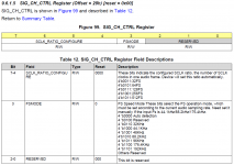
I'm having a deeper look at the datasheet, I don't understand the part attached.
SCLK_RATIO_CONFIGURE [7:4] is used for setting the number of BCK cycles in one audio frame
FSMODE [3] should be one bit only, but then they report 4 bits options in the table... then 3 reserved bits.
it is not even mentioned the corresponding setting of the default value for the first register SCLK_RATIO_CONFIGURE
Attachments
Can you make a function that reads out: 0x39, 0x68, 0x69, 0x70, 0x71, 0x72, 0x73?
Those are the main error/fault/warning registers.
They should read 3, 8, 0, 0, 0, 0, 0 in normal operation.
The registers you mentioned will normally be auto-configured.
Those are the main error/fault/warning registers.
They should read 3, 8, 0, 0, 0, 0, 0 in normal operation.
The registers you mentioned will normally be auto-configured.
For a basic init of tas5825m without any signal processing functions the following sequence will do the job:Next step is to play audio. My idea was the following, already tested with other amplifiers:
- Launch a script with a sequence of I2C writings, bare minimum for playing audio (even bypassing DSP)
0x00, 0x00
0x7f, 0x00
0x4c, 0x30
0x03, 0x03
delay(5 ms)
0x78, 0x80
At least I would set the again in relation to your used power supply voltage to avoid clipping.
- Home
- Amplifiers
- Class D
- TAS5825M based amp