TPA3255EVM - PBTL
Lately, I have been testing the TPA3255EVM in PBTL mode. There is a discussion in the TI forum regarding a modification for optimum performance. Here is the relevant link : TPA3255: Issue When Using PBTL Mode - Audio forum - Audio - TI E2E Community
I am wondering if anybody has used this board in PBTL mode and has applied the above modification.
Attachments
Good Link - Bugger
I didn't use the board in PBTL mode. I used 4 channels, so I didn't have your shut down problem.
It looks like your problem has been documented, but
... bugger...
It's kinda' good to know what the problem is but frustrating that you spent good money and received a "SE Asia" / ebay quality board with problems.
Thanks for sharing!
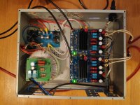
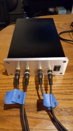
My TI TPA3255 EVM project is gong to make progress. I've bought this SMPS. It provides a DC OK signal at pin 7 of the DCN100 connector that goes high when the PSU works stable. Is there any use for it, for instance to avoid noise when turning the amplifier on or off? How could it be connected to the EVM module in this case?
Best regards!
Best regards!
I first stumbled across this thread today and went quickly through it, but could not find the information I was looking for.
Can two of those blue 3255 boards be attached to one power supply? I have worked with class D amps where a beat tone could be heard when two amps were attached to one power supply.
Has anyone experience with this?
Thanks ahead,
vac
Can two of those blue 3255 boards be attached to one power supply? I have worked with class D amps where a beat tone could be heard when two amps were attached to one power supply.
Has anyone experience with this?
Thanks ahead,
vac
I believe a few users did go with 600w smps and two boards with no consequences, but, financially, the 300 watt smps are very reasonable so I, among most, chose that route. Also it allowed the flexibility to package these separately with short speaker cables in an active arrangement, but my stuff is in a mess, so I'm not doing that yet either, hah.
Last edited:
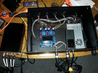
Under pressure to host an 8/10/19 Southeast Michigan gathering of Klipschheads, I finally put my TI TPA3255EVM into a case. Without the ability to split the balanced signal from a Pono player, hooking up my four DIY Anarchy Exodus TH subs was problematic. Now the signal can be passed through to the pair of iNuke 1000s; each one powers a pair of subs.
While the 3255 project languished, I happily listened to a Wiener TPA3118, visible in its case next to the 3255. While I could be happy using that amp as my latest “final” 2-channel amp, listening to the 3255 again reminds me of the difference, even without the subs.
While the 3255 project languished, I happily listened to a Wiener TPA3118, visible in its case next to the 3255. While I could be happy using that amp as my latest “final” 2-channel amp, listening to the 3255 again reminds me of the difference, even without the subs.
Attachments
TPA3255EVM
Hello
Did someone try the second approach and what are your findings?
Enjoy...
ABSNimes, regarding differential input to the 3255EVM board, in stereo BTL mode, there are two slightly different approaches;
i) connect to the J10 and J12 headers (or all 4x RCA connectors, which I consider confusing) -
your audio signals will still be buffered by the NE5532 opamps, but remain fully differential.
ii) connect to pins 11,13,15,17 & 21-GND of the J28 header (as member mboxler suggested)
your audio signals will then bypass the opamps, and go to the TPA3255 simply via a DC blocking cap.
Which approach sounds better will likely depend on whether your particular source device benefits from a buffer in the chain. I suggest you try i) first.
Check your configuration - you want the board in 2 x BTL mode, with differential inputs;
J5(M1), J6(M2) should be in the "0" or "L" position.
J21, J7, J8 should be open.
J4, J19 should be in the "DIFF" position.
J26 should be in the "C" position.
J27 should be in the "D" position.
S1 should be in the "NORMAL" position.
If this works OK, and you want to then try ii)
I understand that the opamps should be grounded, since they will then be unused, and might otherwise generate some noise (or heat).
Hello
Did someone try the second approach and what are your findings?
Enjoy...
I used the first method; it sounds very good, so I stopped there and never tried the second method. It is hard to imagine that these old ears could perceive a difference, so I’ll stick with the way recommended by Texas Instruments.
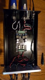
I agree using four RCA connections seems counterintuitive. Nonetheless, that’s how I connected it before putting it in a case (XLR connectors replaced RCA). It helped me to remember that each balanced output consists of a + signal and a - signal. There is no common ground. One RCA pin delivers the + signal and the other RCA pin delivers the - signal, thus two RCAs are needed for each channel. The RCA collars are connected to the shielding, which is connected to ground.
The attached photos show a TPA3118 Wiener amp using four RCAs to accomplish what my 3255 does with a single XLR connector per channel.
Attachments
Last edited:
I first stumbled across this thread today and went quickly through it, but could not find the information I was looking for.
Can two of those blue 3255 boards be attached to one power supply? I have worked with class D amps where a beat tone could be heard when two amps were attached to one power supply.
Has anyone experience with this?
Thanks ahead,
vac
This is what the master and slave mode (plus freq mod interconnect cable) is for with respect to the switching frequency. If you experience the beat note, the two amps need to have the same synchronous modulation in order to prevent it.
Thank you for your kind response. In the meanwhile I have gotten to understand this chip a little better; needed 2x4 channels amplification fast and decided to work with the Chinese boards for reasons of speed and economy.
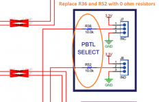
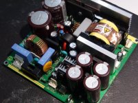
Unsynchronized, they make a lot of noise when put on a single power supply. So some soldering is required to put one in slave mode, and to attach two wires to the synchronization pins, like so

To put a board in slave mode, the 30k resistor has to be removed and a connection has to be made to the chip's on board LDO. Not shown here.
Unsynchronized, they make a lot of noise when put on a single power supply. So some soldering is required to put one in slave mode, and to attach two wires to the synchronization pins, like so
To put a board in slave mode, the 30k resistor has to be removed and a connection has to be made to the chip's on board LDO. Not shown here.
Last edited:


- Home
- Amplifiers
- Class D
- TI TPA3255EVM