There is this - even though the drive caps to the FET gates are undersized - http://nice.kaze.com/popu_d2p_sch.pdf
JL audio also use the D2 in their car audio stuff.
http://www.audiodesign.de/downloads/testberichte2017/TwK-D8.pdf
Lovely UI for their stuff.
https://jlaudio.zendesk.com/hc/en-us/article_attachments/210203787/tun_overview.pdf
http://www.audiodesign.de/downloads/testberichte2017/TwK-D8.pdf
Lovely UI for their stuff.
https://jlaudio.zendesk.com/hc/en-us/article_attachments/210203787/tun_overview.pdf
I'll no longer post here about D2 as I don't want to swamp the SSM thread. They are great little amps. Perfect for Super12s and Super15s.
You know, I think a little bit of info about the intersil chip (or any other fitting dsp chip) is perfectly allright, especially considering the application you are intending it for. This will be a benefit for everyone interested in a reasonably priced multiway setup based on the SSM3582. That is my main goal with the SSM anyway, to hook it up directly to some DSP goodness.
...
When are we ordering PCB's? :-D
Thanks for sharing the schematics. I was looking at newer part with built-in amp and processing. SMM part is quite pricey though you don't need many external components and you can get away with a single power supply. I'm still looking for the simpliest solution for a digital 4-channel amp with DSP and SPDIF input.
When are we ordering PCB's? :-D
I should have the 5ch board complete soon. I could make it 6ch if required. There is room and the supply can handle it. It will then be a case of DNP as the SSM are configured as hardware, mono, 24/96 TDM slots.
Last edited:
... SMM part is quite pricey though you don't need many external components and you can get away with a single power supply. I'm still looking for the simpliest solution for a digital 4-channel amp with DSP and SPDIF input.
Yes! The SSM get's a clear victory when considering the simplicity of the build. Even those 3116's get a bit pricey when you start adding up all the parts and get some decent output filters.
If ordering 50 x SSM3582 they cost 6,11 euros each, that's 10 populated PCB's and ~30 euros for each of those, lets double that for other parts also, so let's guesstimate 60 euros and a bit, maybe max 70 per PCB? I want 2
")
Does not sound very expensive for a low noise 5 way amp with DSP capabilities.
I should have the 5ch board complete soon. I could make it 6ch if required. There is room and the supply can handle it. It will then be a case of DNP as the SSM are configured as hardware, mono, 24/96 TDM slots.
6ch sounds good. 4 is not enough.
24/96 is what I had in mind anyway. Not sure If I can hear any difference at all between 48khz and 96khz.
Edit:
Will it be possible to control the D2 via USB or some thingy?
Looked like a micro USB connector on there, just have to ask.
Edit2:
I just want to ask if you need any money to order parts and such. I'm not rich or anything, just want to help nudge this little project along.
Was thinking if I could send you something through paypal that might be of some help. I'm absolutely not in a rush or anything like that, was actually considering doing this as a more long term project.
Last edited:
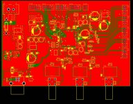
I have several boards on the go using the D2. One is simply a bare bones DSP with no on board amps. Much smaller too. Attached.
2 x sdpif_in (isolated)
1 x spdif_out (isolated)
12 x i2s I/O (including DSD, Intel HD Audio and TDM).
18 x pwm out
simple usb/ftdi programming
balanced line header
The on-dsp ADC is ok. I hope to publish some tests for that soon.
For the powered version previously discussed I'll add another SSM3582 to make 6 channels. In theory I could make a 12ch version with the SSM set to stereo with extra output headers as the d2 supports a 12ch signal flow. At the moment for main power I use a Vicor 120W 8-60v input - 16.0v out CoolPower DC-DC. I added the PIC for USB for programming, LCD headers, buttons and volume control. The USB port supports i2s streaming over USB. I've connected i2s output from the PIC with the DSP providing i2s clock source. We'll see how that goes.
Attachments
Last edited:
If ordering 50 x SSM3582 they cost 6,11 euros each
I was thinking more like 500 at half that! I picked up an Audio Precision to test the boards with. So you'll know what you're getting.
Last edited:
I'm still looking for the simpliest solution for a digital 4-channel amp with DSP and SPDIF input.
Over on Taoabo the DDX-2001 is quite cheap (around $2) and that gives 2 channels. So with two of those and a couple of DIR9001 input modules you'd have the front end for chump change. Then you need output stages depending on how much power you need.
The DDX-2001 comes in SO package so its possible to DIY with the chip, I plan to do that.
STA311B - 8ch. No time domain processing though. If you simply went with 2-channel input then you can mix that to each of the 8 PWM outputs as required.
http://www.st.com/content/ccc/resou.../f9/48/3f/DM00078946.pdf/files/DM00078946.pdf
I like what HIRESFI did with the STA350BW
https://www.youtube.com/watch?v=yY378OZ3Ytc
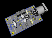
The Audio Processor Workbench from ST is quite good really. I've toyed with that a few times. I designed a 2 x 250W amp using the ST516BE (FFX) with 2ch Speakon output. Pic attached. Not had a chance to build or test it yet though. :-( Might change the input header to dual micro BNC. I'm not sure what I would do with the protection feedback signal. Maybe ignore them! ;-)
Back to the SSM 6ch board. I've added the 6th channel. Hope to have the layout finished Wednesday for you guys to comment. I'm open to any changes!
http://www.st.com/content/ccc/resou.../f9/48/3f/DM00078946.pdf/files/DM00078946.pdf
I like what HIRESFI did with the STA350BW
https://www.youtube.com/watch?v=yY378OZ3Ytc
The Audio Processor Workbench from ST is quite good really. I've toyed with that a few times. I designed a 2 x 250W amp using the ST516BE (FFX) with 2ch Speakon output. Pic attached. Not had a chance to build or test it yet though. :-( Might change the input header to dual micro BNC. I'm not sure what I would do with the protection feedback signal. Maybe ignore them! ;-)
Back to the SSM 6ch board. I've added the 6th channel. Hope to have the layout finished Wednesday for you guys to comment. I'm open to any changes!
Attachments
Last edited:
STA311B - 8ch.
I can't see a viable way to DIY it though, no eval boards on Taobao and package is intractable without dedicated PCB.
I added the PIC for USB for programming, LCD headers, buttons and volume control. The USB port supports i2s streaming over USB. I've connected i2s output from the PIC with the DSP providing i2s clock source. We'll see how that goes.
Yes, that was what it looked like, I just had to ask anyway. Very good with the streaming option, and LCD headers and volume control too! This is like an unexpected treasure chest of stuff, a one pcb complete solution for all sorts of things!
And when you say you're considering 500 chips, this is starting to sound like big things happening.
I know that it's difficult to estimate costs and all that so not going to ask about that, but are you considering selling kits or ... ?
I can't see a viable way to DIY it though, no eval boards on Taobao and package is intractable without dedicated PCB.
Over a decade ago when I was working with in a cellphone repair shop I could change uBGA chips with just ca eyeballing the aim and a steady hand.
If you are thorough it is possible to bake on uBGA chips and the like without proper tooling. Just solder equal amounts of solder on each point on the PCB, rinse and then add flux, put the PCB on a perfectly level heat resistant jig of some sort, carefully and steadily place the chip on the exact spot on the PCB, bake the PCB with a common hot air gun, wait for cooldown, check, rinse and measure. I have done this a few (3) times when the need for urgent repairs have risen, and the proper tooling is far away.
But it is easier to just have it done at a proper repair shop.
Edit:
Some chips have solder on them, so no real need for any pre soldering then. It is however practical to ensure the pads will make good contact, so it may be beneficial to just tin them lightly and then rinse + flux before baking carefully.
Just practice a bit on broken stuff a few times for good measure.
Last edited:
- Status
- This old topic is closed. If you want to reopen this topic, contact a moderator using the "Report Post" button.
- Home
- Amplifiers
- Class D
- What about SSM3582?