I know that it's difficult to estimate costs and all that so not going to ask about that, but are you considering selling kits or ... ?
Depends on the interest really.
So far...
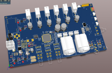
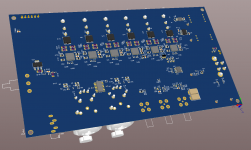
8-60V input supply
D2Audio DAE-6 DSP
6x SSM3582 in mono mode - 24/96 TDM.
XLR input / THAT1280
2 x isolated SDPIF in (micro bnc)
1 x isolated SPDIF out (micro bnc)
1 x stereo headphone out (filtered PWM from dsp - might add op-amp here)
12 x PWM out header
1 x PIC32MX (with attempt at n-channel i2s connection into DSP).
1 x 6-ch i2s/HDA/DSD I/O header.
Volume control knob and some buttons.
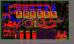
Still need to move things around. The BNC/XLR can come south a bit so the panel mounts are in the right place. Next is a little beautifcation of layout.
Last edited:
If you have a sure-fire way to slap down a 0.5mm QFP on a 0.1" perfboard, I'm all ears.
SMD on a perfboard is a indeed a challenge in itself, I do not see any immediate resolution to your problem, other than just soldering single strands of wire to each pin. Just a small tip (almost like a blunt needle), maybe 0,3mm thin solder and a microscope and you're good to go. Problem is cooling, but you could use thicker strands where many pins serve the same purpose, like for instance ground. On the other side of the wire strands just solder them onto the board, if you have a few cm strands the temperature will cool enough that they will not loosen from the pins on the chip.
Please note I have not done this on ALL the pins on a single chip, but only instances where maybe up to 5-6 the PCB traces where burnt and I had to fix the contact points. But I am certain it is possible, provided you have a bucket of patience handy.
Edit:
In case of anger, make sure you channel it to increase focus on solving the problem. Like current, it needs to go somewhere. 🙂
Last edited:
Routing starts today. Will update you Friday.
Looking forward to it! 🙂
How is the mountain thing coming along?
Mountain thing?
I am sorry about the poor reference, it was about Intersil and the software for programming the DSP.

Yes, 6. I'm indecisive about the combo xlr and internal ADC.
Yes, I second your indecisiveness so to speak, do not use those myself, but many designs have them, so someone must use them, right?
They are for AES/EBU I presume.
I have some optical spdif stuff, but can just get a optical->coax thingy, so not an issue.
They're analog XLRs using the ADC withing the DSP. Spec sheet claims -81dTHD+N / 94db SNR. Nothing to write home about.
Well, I guess you could always just add another adc, unless you feel it's complicating things. Been looking at the CS5381 good specs but it's a bit pricey at 27euros each.
http://www.mouser.com/ds/2/76/CS5381_F2-15415.pdf
The CS5361 is a bit cheaper.
http://www.mouser.com/ds/2/76/CS5361_F2-48097.pdf
The PCM1803 (or possibly the 1802) is sort of middle of the road and around 3 euros for one. Do note they are single ended, but specs look fine for the intended purpose, and it seems a simpler way to improve things, less tracks.
http://www.ti.com/lit/gpn/pcm1803a
My vote goes to the PCM1804, it's cheap, differential input and good enough specs.
www.ti.com/lit/ds/symlink/pcm1804.pdf
But I have no experience with ADC, so my opinion is really not worth anything in this matter.
Still eagerly awaiting any news on the SSM3582 thingy.
I do not expect any upgrade on the ADC (...?). Still looking around for other boards with this chip, should be fine to bake it on a PCB using the center pad and some "guide" and then just solder all'round with a thin tip, considering trying it out but have not made room for a proper work bench at home yet, got to get rid of some stuff first.
Sad news on my part is still declining amount of time availible to spend on audio related things, and I had to find a substitute for my rocking chair from the late 1800s as the straps under the seat upholstery tore. It's been nearly broken since I was a little boy, but now it's time to fix it, just got to figure out how. Got a "new" chair hardly used for a small amount of money, very comfy but I'll be surprised if it lasts 10 years.
This post is just as much for my own reference as anyone else that migh be interested. Please do correct me is any of my assumptions are wrong, there is much of that here. 🙂
Considering making a PCB for the SSM3582 myself, have not done this since school, but it will probably be a good learning experience. Other than the chip itself I will opt for some Murata NFZ2MSM181 just to be on the safe side, Some 220-470uF caps for PSU just to be safe, and a number of assorted SMD caps in the values 220pF 0,1uF 10uF and 20uF.
The SSM3515 is the closest brother to the SSM3582, performance is not as good in low z conditions, but it comes in UFBGA package and should be easier to work with. SSM3582 is still my preffered chip however, and the WFQFN package should be easy enough to bake on a PCB at home with not too much effort.
According to this (now probably ancient) document on PCB design:
http://www.ti.com/lit/an/szza009/szza009.pdf
It should be possible to get 95% of the EMI suppression of a 4 layer PCB in a 2 layer version. A further "guesstimation" on my part concludes that it should be possible to achieve 87% of a 6 layer design, in 2 layers. So while every % lost is a sacrifice in the end product, it still might be for the best, since simplicity of the design is a personal preference, especially considering my PCB design skills are 0% and doomed to increase no matter what the final outcome might be.
So reading up on documents, and familiarizing myself with the free Eagle PCB design tool is my current undertaking. At the very least it would be interesting to see if a 4 x SSM3582 in mono on one board could come out of this. Just need 2 for a 4 way stereo setup then.
I have also just completed a design using the CM6632A and 5 x SSM3582 for a 10ch usb attached amplifer.
Highlights
OV/UV supply protection using LTC4365
Isolated active circuit using LTM2884 USB isolator
CM6632A as i2c master
Golledge GXO-3306L/A 49.152 and 45.158 clocks for 88/96 audio
5 x SSM3582 in i2s stereo mode for 10ch output
Images to follow. 🙂
Highlights
OV/UV supply protection using LTC4365
Isolated active circuit using LTM2884 USB isolator
CM6632A as i2c master
Golledge GXO-3306L/A 49.152 and 45.158 clocks for 88/96 audio
5 x SSM3582 in i2s stereo mode for 10ch output
Images to follow. 🙂
I have also just completed a design using the CM6632A and 5 x SSM3582 for a 10ch usb attached amplifer.
Highlights
OV/UV supply protection using LTC4365
Isolated active circuit using LTM2884 USB isolator
CM6632A as i2c master
Golledge GXO-3306L/A 49.152 and 45.158 clocks for 88/96 audio
5 x SSM3582 in i2s stereo mode for 10ch output
Images to follow. 🙂
!
Very interested in this!
So it will basicly work as a 10 channel out external sound card then?
On my part:
I did not get very far at all, other than I learned that i2s is much easier to succeed with than TDM, and the closest component that I found an existing part for in a Eagle library is the SSM3302, will need to edit the part first, have not got around to it, just been reading and finding info. I have a very clear PCB layout in my head that's very realistic and simple, with voltage regulators on board and the SSM3382 sitting between 2 speaker terminals attached to the chassis, so the speaker terminals are holding it in place. A row of 4 SSM3582 with speaker terminals above and below each chip, and just braided wires for i2s connectivity, to ease PCB design. This allows for one solid ground plane, and almost one solid v+ plane too, except for components and traces to connectors (which fit very closely by both the cips and the voltage regulators).
Edit:
And I found the perfect transformer in the trash at work today! Just a thingy with one output, but selectable 15V and up to 21V taps I think it was, and its 125VA, perfect for a voltage regulator board with some LM338 or possibly the LM350. And I have been fantasizing about using a 2x18V 300VA toroid that's laying about to make a dual mono psu, or something. At least the LM338 seems to have the best data when regulating around 10v down, or at least that's the impression I got.
Last edited:
- Home
- Amplifiers
- Class D
- What about SSM3582?