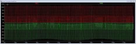
This is a fast power stage transition.
But actually fastness is much less important than precisely 0 dead time.
15 Ns is indeed very fast fall time.
Last edited:
Thanks Pafi for the help,
I try my best, however this is very hard.
I do now that for simulation there is a need for good models and including of pcb induction and parasitics, however it is always a need to build and test, with modern parts this is quite easy to get good goals.
Interesting. I'm never satisfied with all of the results.
The power comparator I do use in simulation is the version from the article I have send already, it uses rf parts for fast transitions, the death time is adjusted with gate resistors.
Gate resistors with invisible values on your picture. Don't you want to give chance to correct the mistakes?
For the bang and bang, I use always a laboratorium supply, who do switch of when things go wrong, it have help me a lot in past to prevent costs for blown parts.
(So instead of blowing it will be simply non-operating. Is this the goal, or a correctly working amp?)
This protection may work well for ClassA, etc...
I don't think some blown parts was a problem during experimentation, but lets make some basic calculation:
Normal output current can be 40V/8ohm=5A. You must set higher current limit than this. Cross-conduction current (flowing from +40V to -40V) must be smoothed by decoupling caps, and your lab psu can limit the average value of it. So the maximal possible idle dissipation will be 80V*5A=200W. Will IRF540 survive? Maybe.
But I go use your advise, I am not complete oke with ltspice, however I have also multisim who is more easy but as demo so not such big schematics.
For as the article did say about death time, changing the resistors did not do much in simulation, you did mention a while back that the 200 ohm resistor has to be swapped.
200 ohm? I don't remember anything like this.
I think you should try to understand how dead time setting works. "Did not do much"? What do you mean? Did you try to change charging resistor to 50 ohm and discharging resistor to 1 ohm and cross conduction current didn't become much lower?
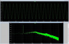
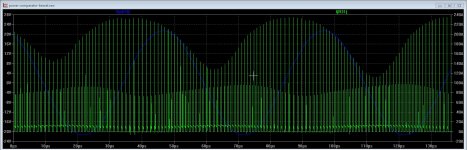
Lets assume this is true. So...?The power comparator has very fast rise and fall times.
Last edited:
I try my best, however this is very hard.
Interesting. I'm never satisfied with all of the results.
Gate resistors with invisible values on your picture. Don't you want to give chance to correct the mistakes?
(So instead of blowing it will be simply non-operating. Is this the goal, or a correctly working amp?)
This protection may work well for ClassA, etc...
I don't think some blown parts was a problem during experimentation, but lets make some basic calculation:
Normal output current can be 40V/8ohm=5A. You must set higher current limit than this. Cross-conduction current (flowing from +40V to -40V) must be smoothed by decoupling caps, and your lab psu can limit the average value of it. So the maximal possible idle dissipation will be 80V*5A=200W. Will IRF540 survive? Maybe.
200 ohm? I don't remember anything like this.
I think you should try to understand how dead time setting works. "Did not do much"? What do you mean? Did you try to change charging resistor to 50 ohm and discharging resistor to 1 ohm and cross conduction current didn't become much lower?
Lets assume this is true. So...?
Let,s do something make clear for you.
The 200 ohms was 20 ohms, and for the supply after first try I have a normal supply also 2 x 55 volts 10 amps to try, and maybe you are right the supply do not work with switching amps because it is completely different.
Has you not see the schematic? of the comparator? it is here in previous post where you mention about the gate resistor setup.
Death time is just a delay, between both mosfets as I also have in the smps supply simulation, it is however a part of the controller and easely to setup.
Don't take me al to serious because I do only look at it and study some, I have a idea that this power transmitter do well in audio quality, but has still a bad name.
For supply I do setup it for switching only and when this do well I set up the power supply for further testing.
regards
Attachments
Last edited:
Let,s do something make clear for you.
The 200 ohms was 20 ohms,
I know. But 200 is not 20. And you also told you've already swapped it back, and it made operation better. So this is doubly contradictional.
and for the supply after first try I have a normal supply also 2 x 55 volts 10 amps to try, and maybe you are right the supply do not work with switching amps because it is completely different.
I don't understand anything about this.
Has you not see the schematic? of the comparator? it is here in previous post where you mention about the gate resistor setup.
I've seen. The original one with the swapped values. Also seen your screenshot with INVISIBLE VALUES (however it was NOT in previous post, nevermind). Why I have to write everything twice or more???
Thank you for finally showing the gate resistors, but it is different from everything you showed before, so i still have no idea what you actually simulated.
Death time is just a delay, between both mosfets as I also have in the smps supply simulation, it is however a part of the controller and easely to setup.
It's not time to death. Please don't die! I have no idea what do you mean "it is just a delay", and if it is easy to set, then why haven't you done it yet.
I guess you have absolutely no idea why dead time is important for ClassD. It is the most important factor for linearity and efficiency.
Don't take me al to serious because I do only look at it and study some,
I understand nothing about this.
I have a idea that this power transmitter do well in audio quality, but has still a bad name.
Bad name? No idea what you mean again.
For supply I do setup it for switching only
I guess you want to tell something, but I can't figure out what.
and when this do well I set up the power supply for further testing.
regards
Good luck! I don't understand this either, but it sounds like some real test.
Attachments
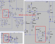
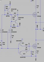
This is the real one, I have put part value in it where it can not be seen properly.
And now I have today get the parts for the circlotron and go on with it, that one do wel, do play and very good, I go however go play with that D stuff, what I did mean on bad name is that it is writting such in high end world, but she get better every day and maby because of stupid guys like me play with it and discover something new.
regards
Attachments
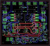
This is the real one, I have put part value in it where it can not be seen properly.
The original schematic in the article is clearly visible, no need to write on it anything. But 2 values are swapped. I write this for 4th time.
The visibility and consistency problem I wrote is about your simulated versions.
And now I have today get the parts for the circlotron and go on with it, that one do wel, do play and very good,
Did you solved the measurement problem?
what I did mean on bad name is that it is writting such in high end world, but she get better every day
I don't know the top-of-class typewriter android-lady you mentioned, but I hope she will be healthy soon and can change her name.
") Is she a relative of the 200 years old man (written by Asimov)?
Is she a relative of the 200 years old man (written by Asimov)?The original schematic in the article is clearly visible, no need to write on it anything. But 2 values are swapped. I write this for 4th time.
The visibility and consistency problem I wrote is about your simulated versions.
Did you solved the measurement problem?
I don't know the top-of-class typewriter android-lady you mentioned, but I hope she will be healthy soon and can change her name.
I have already swapped them as you did say, but for death time, it also slows down switching when use gate resistors for it, it forms a low pass with the mosfet, so when low gate capacitance the resistor needs bigger.
But first I go on with the circlotron one, later on I go experiment with class D because I have heard bad things, but also very good things as it sounds very sweet, the only way to get convinced is build one coming months.
I did smps builds, last was a 160 amps welder inverter, and winding the transformer was the most challencing, so when I can build smps I shure can build class D.
Have a nice weekend.
regards
Did you solved the measurement problem?
I have ordered a pcb for that, I need go from balanced to unbalanced, and a chinese board will do, with some more changes I have also a floating probe for scope, that come in handy.
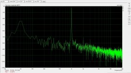
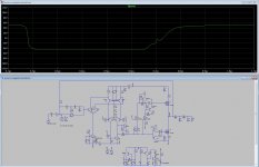
Arta with output 20 volts peak (one half of circlotron so it is 40 volts) and 8 ohm load, with capacitive load it do not change much, just some 4 dB more hd.
But need a good audio card because this is with the pc board chip.
Attachments
Last edited:
I have already swapped them as you did say, but for death time, it also slows down switching when use gate resistors for it, it forms a low pass with the mosfet, so when low gate capacitance the resistor needs bigger.
Obviously. This is how this kind of dead time setting works. This is why I set dead time before gate driver.
But need a good audio card because this is with the pc board chip.
Why do you think your soundcard was not good enough? Have you measured its own distortion?
But you are right, maybe a driver ic is better because when do death time with gate resistors the fall and risetimes als get worse making the output les balanced, however the authors of the power comparator has do make a fast one, 100nS is quite fast for a discrete one.
I have to search for a good model for the IR series gate drivers.
I have to search for a good model for the IR series gate drivers.
In my travels I spotted this 4.5ns comparator - MAX999. May or may not be useful.
https://www.maximintegrated.com/en/products/analog/amplifiers/MAX999.html
https://www.maximintegrated.com/en/products/analog/amplifiers/MAX999.html
Why do you think your soundcard was not good enough? Have you measured its own distortion?
The card has low distortion but one input is not oke, I have now a differiential pcb for meaqsuring the ciclotron output, single did not work, dc was the cause.
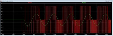
By the way I have experiment with the death time and shoot through, also I did some tryouts with a chip IR2110 with ot pcb design is quite more easy because much is in the chip itself, however I have get it not to work I think the pspice model is bad, so if you guys have one model of a fast gate driver, can I get it, thanks.
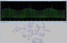
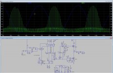
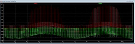
Pictures is with differend resistors, the best and lowest has a 200 ohm one, however the speed get affected who is normal when rising a gate resistor forming a speed reduction with mosfet capacitance.
regards
Attachments
Last edited:
Ultrafast comparators increase noise. Not recommended, unless a preamp precedes it.
comparator delay's also affect oscillation frequency
, if to fast it go to high, feed forward do not always correct that, I did try, but when using with a triangle input the old way it is how faster the better.
Last edited:
comparator delay's also affect oscillation frequency
Obviously. This is an old story, and not related to what I wrote.
but when using with a triangle input the old way it is how faster the better.
Really? Have you actually built it, and measured noise?
When evaluating my first class D-amp designs I found that slow comparators like LM393 produce lots of noise, which could be reduced significantly by replacing them by fast video bandwidth comparators.
As these things never are specified in any data sheet, this was a pure trial and error procedure - some maxim parts proved to work nice.
As these things never are specified in any data sheet, this was a pure trial and error procedure - some maxim parts proved to work nice.
Obviously. This is an old story, and not related to what I wrote.
Really? Have you actually built it, and measured noise?
No but there are papers about it who says when using a triangle carrier you need a fast comparator and opamp to make one, and to get as lineair asd possible, however the new self oscillation amps did push them to the background.
I am not agree that these fast compatators are causing more noise, I am more concern about pcb design, there is the cause of the most trouble.
On picture I get the comparator have fast fall times but slower risetimes, this is due to the bigger gate resistors to get less shoot through, I think that also for the pcb is to use gate driver ic,s who do make it much easy to design a clean pcb.
As for your question if I did try things, no, I do read much about the technology and have not yet plans to go experiment, first I want get ready with the circlotron.
On other pictures U see shoot trough sims, however I need to make the resistor quite big and therefor it has lower risetimes, who is normal but it is quite much, I think that for this only build one is better then sim.
regards
Attachments
The card has low distortion but one input is not oke, I have now a differiential pcb for meaqsuring the ciclotron output, single did not work, dc was the cause.
By the way I have experiment with the death time and shoot through, also I did some tryouts with a chip IR2110 with ot pcb design is quite more easy because much is in the chip itself, however I have get it not to work I think the pspice model is bad, so if you guys have one model of a fast gate driver, can I get it, thanks.
Pictures is with differend resistors, the best and lowest has a 200 ohm one, however the speed get affected who is normal when rising a gate resistor forming a speed reduction with mosfet capacitance.
regards
the ir2110 lm311 ltspice models .other d models too have fun simulating
Attachments
-
Increased noise with multiple modules - Page 5 - diyAudio UcD6.zip2 KB · Views: 46
-
Tekko goes crazy - Page 6 - diyAudio LTspice models and subcircuits by Tekko (diyAudio).zip7 KB · Views: 58
-
Tekko goes crazy - Page 6 - diyAudio UcD simplified.zip180 KB · Views: 65
-
My NON-discrete SODFA class-D amp - Page 12 - diyAudio ir2011_test.zip2.9 KB · Views: 61
-
spice class d models etjale.zip5.3 KB · Views: 52
-
spice class d models etjale,sovadk ,etc.zip13.1 KB · Views: 57
- Status
- This old topic is closed. If you want to reopen this topic, contact a moderator using the "Report Post" button.
- Home
- Amplifiers
- Class D
- Class D investigation.