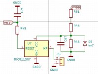
I have simulated the anti-pop circuit and it looks like it works well.
There's a 10ms delay between flicking the switch and going low, I don't think that will be a problem.
I use in next amp this antipop circuit , MIC8114TUY-TR
Attachments
Last edited:
I assure you that in my stash are fake NE5532 I bought in Germany several years ago. These showed about 30dB more noise than the originals, bandwidth and DC - power consumption fitted perfectly to the cheapest op-amp ever - the LM358. These are re-labelled by the clever business people. That is quite common nowadays. And yes, you can really hear the difference!
I do not doubt you in the least. Unscrupulous sellers fake most everything.
I receive the packed from mouser today.
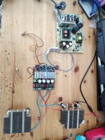
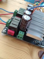
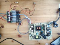
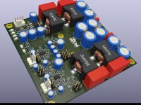
I solderd all caps. So I have now KYB 63V 1800uF on amp and psu. Todaly capacity is 12600uF. Stock was 6460uF.
For the filter I mounted new MKS4 caps because the TDK will be delivered only on july :-(
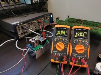
Later I will turn the beast on and made some mesurement with my 8ohm resistors
I solderd all caps. So I have now KYB 63V 1800uF on amp and psu. Todaly capacity is 12600uF. Stock was 6460uF.
For the filter I mounted new MKS4 caps because the TDK will be delivered only on july :-(
Later I will turn the beast on and made some mesurement with my 8ohm resistors
Attachments
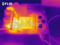
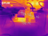
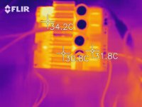
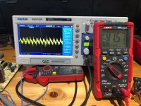
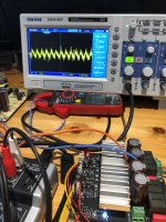
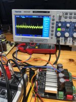
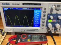
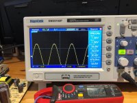
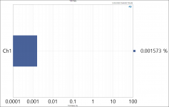
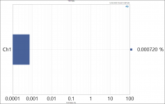
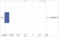
So I did the measurement... What you want to know others?
Attachments
-
 WhatsApp Image 2020-05-22 at 21.18.56(5).jpeg132.9 KB · Views: 127
 -
 WhatsApp Image 2020-05-22 at 21.18.56(1).jpeg135.2 KB · Views: 115
 -
 WhatsApp Image 2020-05-22 at 21.18.56.jpeg143 KB · Views: 134
 -
 WhatsApp Image 2020-05-22 at 21.15.38(1).jpeg342.5 KB · Views: 104
 -
 WhatsApp Image 2020-05-22 at 21.15.38.jpeg353 KB · Views: 110
 -
 WhatsApp Image 2020-05-22 at 21.15.37.jpeg353.7 KB · Views: 102
 -
 WhatsApp Image 2020-05-22 at 21.15.36.jpeg331.4 KB · Views: 111
 -
 WhatsApp Image 2020-05-22 at 21.15.36(1).jpeg368.7 KB · Views: 192
I use in next amp this antipop circuit , MIC8114TUY-TR
Thanks, I see that Rohm bd52exxg or bd53exxg is cheaper and has an adjustable time delay. 750ms is pretty long.
You could try that next time if you don't need a push button.
Unfortunately, I bought my parts already, will test out the previous circuit first.
Last edited:
.My new TPA215x amp
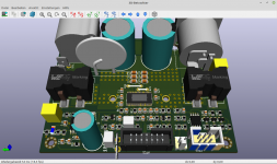
Very neat design. I wonder about heat dissipation of your linear regulator? At the time I am finalizing my own kiCAD design. It is a PBTL mono block specially designed for battery powered mobile amplification. It provides a low-noise 12V switching regulator, under voltage lockout for battery protection and automatic shutdown after a longer signal pause. These peripheral functions are provided by an Atmel Attiny25. Additionally this 8pin CPU manages TPA3255 error handling including anti-plopp control. The heatsink is relativily small designed for up to 100W into 8 Ohms. For max flexibility the driving AFE is separated on a 5cm by 5cm daughter board.
This is very interesting, share?These peripheral functions are provided by an Atmel Attiny25. Additionally this 8pin CPU manages TPA3255 error handling including anti-plopp control.
Hi Fellow TPA builders!
I've been plugging away on my monoblock PBTL design and have had both some awesome successes and some frustrating issues.
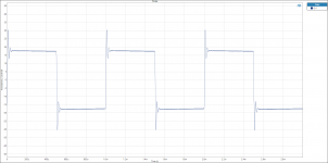
Overall, and after much fussing about, I got everything up and working, but only for between 16 and 27 seconds")
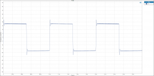
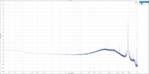
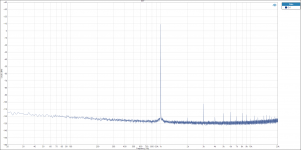
Performance is very promising, with the lowest THD numbers I've seen to date from a TPA, so functionally, everything is working as one would expect. The PFFB implementation works, and overshoot is well within the levels suggested in the TI white paper. The amp is oscillating correctly at 450kHz, and literally everything is perfect... except only for ~20 seconds before the amplifier shuts down.
Here's where I'm hoping someone out there with more experience with the TPA can perhaps lend some advice
Here's the situation:
1. The amp starts up exactly as expected. I'm running PVDD at 24V at the moment, but have also run it at 51V. PVDD comes up first, the 15V buck comes up next which supplies the two dedicated 12V linear regs for VDD and GVDD. Both are rock solid at 12.1V. The front end also comes up provided by the dual rail LTC3265 regulator set for +/-12V.
2. There are absolutely no clicks or pops on startup or shutdown. The supplies seem to come up and down elegantly enough not to require any startup delay. This is probably helped along by the bipolar front end. I have made no connection at all to /RESET so it is not asserted low during startup.
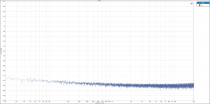
3. If I feed a signal to the amp, it works perfectly. Performance into 8 ohms is exceptional, and noise is respectably low... exactly the same as the published figures from the TI white paper.
4. After ~20 seconds (sometimes 16, sometimes 27) the amp just shuts down. All power supplies are still up, none of them glitched, the output stage appears to be in high-Z mode and power draw drops down to about 1.9W for the whole board which is basically the AFE power draw and the regulator losses.
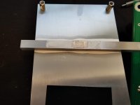
The first thing I thought of was thermals... clearly the TPA was heating up, hitting thermal shutdown and disabling the outputs. I figured I could run it without a heatsink at 24V and with only an 8ohm load at 1W for testing as it's easier to access the board for probing and measurements. So, I added the full size heatsink, mounted everything up, and I got the exact same outcome. Shutdown after ~20 seconds. I removed everything and made a small aluminum interface block and held it on the top of the IC with thermal compound. I can hold my finger on this the whole time and it does not heat up at all... indicating the amp is definitely not hitting its thermal limits.
So.... what's the deal? Has anyone seen this before? My understanding of the datasheet is that there is an internal pull-up on the /RESET pin and short of asserting it low to prevent transients on startup and shutdown, this pin should be able to hold itself high and keep the amplifier running with no connection. Is this a correct understanding?
Is it possible the amplifier got hot enough under the above conditions that the die somehow detached from the power pad internally? That's the only other explanation I can come up with.
My next course of action is to remove the TPA from the board and solder on a fresh one, but I'd rather not go through that if it's something else simple that I've overlooked.
I have attached here everything I can think of that might be of use in troubleshooting, but anyone can think of anything it might be, I would be happy to try and provide additional details.
It's incredibly frustrating to see everything working so well, but not even have enough time to give these a proper listen and run high power testing.
Additional pertinent info:
- The output load and output power doesn't seem to make any difference to the shutdown time. I've tried with no load, no signal, and a 4ohm load with 50W output and the difference in shutdown time is only a few seconds... 21 vs. 17 respectively.
- The TPA power draw at idle (while oscillating) is 1.41W with 24V PVDD and an 8 ohm load attached. This includes any losses in the 12V linear supplies and the 15V buck.
- With PVDD set to 51V, the amp only stays on for about 10 seconds. Everything still works as expected, and performance is still excellent, but time before shutdown is much shorter.
Regards,
Owen
I've been plugging away on my monoblock PBTL design and have had both some awesome successes and some frustrating issues.
Overall, and after much fussing about, I got everything up and working, but only for between 16 and 27 seconds
Performance is very promising, with the lowest THD numbers I've seen to date from a TPA, so functionally, everything is working as one would expect. The PFFB implementation works, and overshoot is well within the levels suggested in the TI white paper. The amp is oscillating correctly at 450kHz, and literally everything is perfect... except only for ~20 seconds before the amplifier shuts down.
Here's where I'm hoping someone out there with more experience with the TPA can perhaps lend some advice
Here's the situation:
1. The amp starts up exactly as expected. I'm running PVDD at 24V at the moment, but have also run it at 51V. PVDD comes up first, the 15V buck comes up next which supplies the two dedicated 12V linear regs for VDD and GVDD. Both are rock solid at 12.1V. The front end also comes up provided by the dual rail LTC3265 regulator set for +/-12V.
2. There are absolutely no clicks or pops on startup or shutdown. The supplies seem to come up and down elegantly enough not to require any startup delay. This is probably helped along by the bipolar front end. I have made no connection at all to /RESET so it is not asserted low during startup.
3. If I feed a signal to the amp, it works perfectly. Performance into 8 ohms is exceptional, and noise is respectably low... exactly the same as the published figures from the TI white paper.
4. After ~20 seconds (sometimes 16, sometimes 27) the amp just shuts down. All power supplies are still up, none of them glitched, the output stage appears to be in high-Z mode and power draw drops down to about 1.9W for the whole board which is basically the AFE power draw and the regulator losses.
The first thing I thought of was thermals... clearly the TPA was heating up, hitting thermal shutdown and disabling the outputs. I figured I could run it without a heatsink at 24V and with only an 8ohm load at 1W for testing as it's easier to access the board for probing and measurements. So, I added the full size heatsink, mounted everything up, and I got the exact same outcome. Shutdown after ~20 seconds. I removed everything and made a small aluminum interface block and held it on the top of the IC with thermal compound. I can hold my finger on this the whole time and it does not heat up at all... indicating the amp is definitely not hitting its thermal limits.
So.... what's the deal? Has anyone seen this before? My understanding of the datasheet is that there is an internal pull-up on the /RESET pin and short of asserting it low to prevent transients on startup and shutdown, this pin should be able to hold itself high and keep the amplifier running with no connection. Is this a correct understanding?
Is it possible the amplifier got hot enough under the above conditions that the die somehow detached from the power pad internally? That's the only other explanation I can come up with.
My next course of action is to remove the TPA from the board and solder on a fresh one, but I'd rather not go through that if it's something else simple that I've overlooked.
I have attached here everything I can think of that might be of use in troubleshooting, but anyone can think of anything it might be, I would be happy to try and provide additional details.
It's incredibly frustrating to see everything working so well, but not even have enough time to give these a proper listen and run high power testing.
Additional pertinent info:
- The output load and output power doesn't seem to make any difference to the shutdown time. I've tried with no load, no signal, and a 4ohm load with 50W output and the difference in shutdown time is only a few seconds... 21 vs. 17 respectively.
- The TPA power draw at idle (while oscillating) is 1.41W with 24V PVDD and an 8 ohm load attached. This includes any losses in the 12V linear supplies and the 15V buck.
- With PVDD set to 51V, the amp only stays on for about 10 seconds. Everything still works as expected, and performance is still excellent, but time before shutdown is much shorter.
Regards,
Owen
Attachments
-
 Scope3.PNG63.5 KB · Views: 100
 -
 Scope4.PNG64.1 KB · Views: 102
 -
 FFT_FULL_BAND.PNG110.1 KB · Views: 110
 -
 FFT_NO_INPUT.PNG112 KB · Views: 119
 -
 The Wire Class D - FFT 1W 8R PFFB 1kHz CODACA.png101.9 KB · Views: 112
 -
 THD Ratio 2.PNG73.5 KB · Views: 434
 -
 THD Ratio 4.png73.5 KB · Views: 422
 -
 The Wire Class D - THD Ratio 1W 8R PFFB 1kHz CODACA.png71.8 KB · Views: 450
 -
 TPA_TESTING.jpg470.2 KB · Views: 444
 -
 HEATSINK.jpg241.1 KB · Views: 123
For anyone looking for the schematic and placement, they can be found here from a previous post:
TPA3255 - all about DIY, Discussion, Design etc.
Regards,
Owen
TPA3255 - all about DIY, Discussion, Design etc.
Regards,
Owen
Did you monitor the error outputs of the TPA during the whole period until shutdown? Do read the chapter "error reporting" .
Is overtemp warning active before shutdown?
The fact that active phase reduces at high supply voltage looks like an indicator of overheating to me.
Is overtemp warning active before shutdown?
The fact that active phase reduces at high supply voltage looks like an indicator of overheating to me.
Show reset circuit
There is no reset circuit. The /RESET, /FAULT, and CLIP_OTW pins are all floating.
Did you monitor the error outputs of the TPA during the whole period until shutdown? Do read the chapter "error reporting" .
Is overtemp warning active before shutdown?
The fact that active phase reduces at high supply voltage looks like an indicator of overheating to me.
I can solder a few flying leads on to monitor the CLIP_OTW and /FAULT pin and see if they indicate an overtemp. I get the feeling it will, so I'm more curious about why that would be given the IC appears to be operating correctly and is properly mounted to a large heatsink.
I may just try and replace the TPA with a new one... assuming something has gone batty with the one mounted in there now.
Regards,
Owen
I soldered up some flying leads to /RESET, /FAULT, and /CLIP_OTW this evening and the results were a bit surprising for me.
/FAULT and /CLIP_OTW are both 3.3V before the shutdown event, and both remain at 3.3V after the shutdown. After a shutdown has occured, I can ground /FAULT and the amplifier will re-start for another 10-20s round before shutting down again.
During the above process I shorted one of the three pins to the 24V rail and cooked the TPA, but also interestingly, a new TPA part I just soldered in is now behaving pretty much the same way, except shutdown time is now more like 11 seconds, and this chip has never been run without a proper heatsink.
Have to say... I'm baffled. I'll sleep on it, but that's the update for tonight!
Regards,
Owen
- Home
- Amplifiers
- Class D
- TPA3255 - all about DIY, Discussion, Design etc