another amp
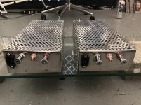
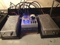
Here’s my second multi-channel amp based on Apex Microtechnology power op amps. The first one used the PA07 chip and was built about two years ago (post #3200-3202). This one uses the PA12 chip which has a higher current output at +/- 15 Amps while running from a +/- 50V power supply. This amp is a dual 4 channel configuration which puts out about 240 Wrms per side. It was designed for an active crossover system with a 4 ohm sub and a 2-way MTM speaker on each side. Each driver get it’s own dedicated amp channel, which together with the active crossover, sounds very nice, IMHO.
Here’s my second multi-channel amp based on Apex Microtechnology power op amps. The first one used the PA07 chip and was built about two years ago (post #3200-3202). This one uses the PA12 chip which has a higher current output at +/- 15 Amps while running from a +/- 50V power supply. This amp is a dual 4 channel configuration which puts out about 240 Wrms per side. It was designed for an active crossover system with a 4 ohm sub and a 2-way MTM speaker on each side. Each driver get it’s own dedicated amp channel, which together with the active crossover, sounds very nice, IMHO.
Attachments
New amp photos
Folks:
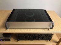
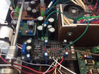
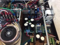
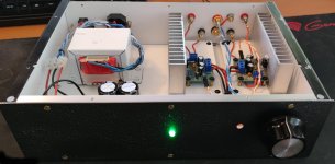
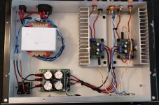
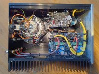
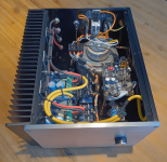
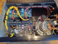
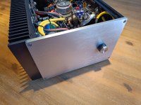
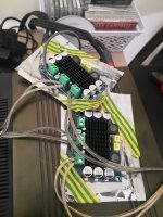
I resurrected a failed project five or six months ago, stripping out a clunky amp and buffer and replacing it with a Super Gain Clone amp and an RK27 attenuator. It sounded great but there was room for improvement (both literally and figuratively), so I added B-Board buffers (designed by RJM Audio), voltage regulation and some additional power supply capacitance. I had an extra DACT CT2-20 attenuator on hand, so it was swapped in for the RK-27.
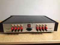
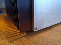
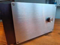
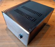
The first photo shows the amp with just the Super Gain Clone amp. The remaining photos were taken after the B-Boards, voltage regulators, additional capacitor bank and DACT were shoveled in.
Sounds terrific. An old broken project has been reborn!
Regards,
Scott
Folks:
I resurrected a failed project five or six months ago, stripping out a clunky amp and buffer and replacing it with a Super Gain Clone amp and an RK27 attenuator. It sounded great but there was room for improvement (both literally and figuratively), so I added B-Board buffers (designed by RJM Audio), voltage regulation and some additional power supply capacitance. I had an extra DACT CT2-20 attenuator on hand, so it was swapped in for the RK-27.
The first photo shows the amp with just the Super Gain Clone amp. The remaining photos were taken after the B-Boards, voltage regulators, additional capacitor bank and DACT were shoveled in.
Sounds terrific. An old broken project has been reborn!
Regards,
Scott
Attachments
@SRMcGee
I looked at the first picture without reading your post and thought "wow, there's a lot going on here", and then I clicked on the other pictures...
I also looked up the attenuator you're using and it's way more expensive than my entire amp
A more general question to people here: how warm should a transformer get? I know mine is undersized for the stereo LM1875 (2x16V 2A) but I mostly run it pretty quiet, still, after a couple hours it's toasty.
I have an overkill toroid on the way so it's just my curiosity.
Attachments
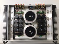
hidetaka, is there a perforated cover (planned) for this amp? While an”overkill” toroid power Xfmr might cool down that side of the amp, the heatsinks for output chips will need something more than just chassis radiation to be most effective. Frankly they’d probably work much better on the outside of the chassis, but if you want to contain them within, I don’t think it’d hurt to drill a few dozen small holes on bottom plate to facilitate a flow-through chimney effect. You’d be hard pressed to provide too much ventilation, but the opposite is certainly not the case.
How hot is it? Can you keep your hand on it for 10+ seconds without burning? My 3886 runs very cool and the heatsink INSIDE the chassis never gets very hot. But that's a different thing from TOO hot. Too hot is - rule of thumb here - ideally you can keep your hand on the transformer for as long as you want. But...it can get even hotter than that and be OK (depending on the transformer and other considerations.
@SRMcGee
I looked at the first picture without reading your post and thought "wow, there's a lot going on here", and then I clicked on the other pictures...
I also looked up the attenuator you're using and it's way more expensive than my entire amp
A more general question to people here: how warm should a transformer get? I know mine is undersized for the stereo LM1875 (2x16V 2A) but I mostly run it pretty quiet, still, after a couple hours it's toasty.
I have an overkill toroid on the way so it's just my curiosity.
@chrisb
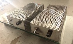
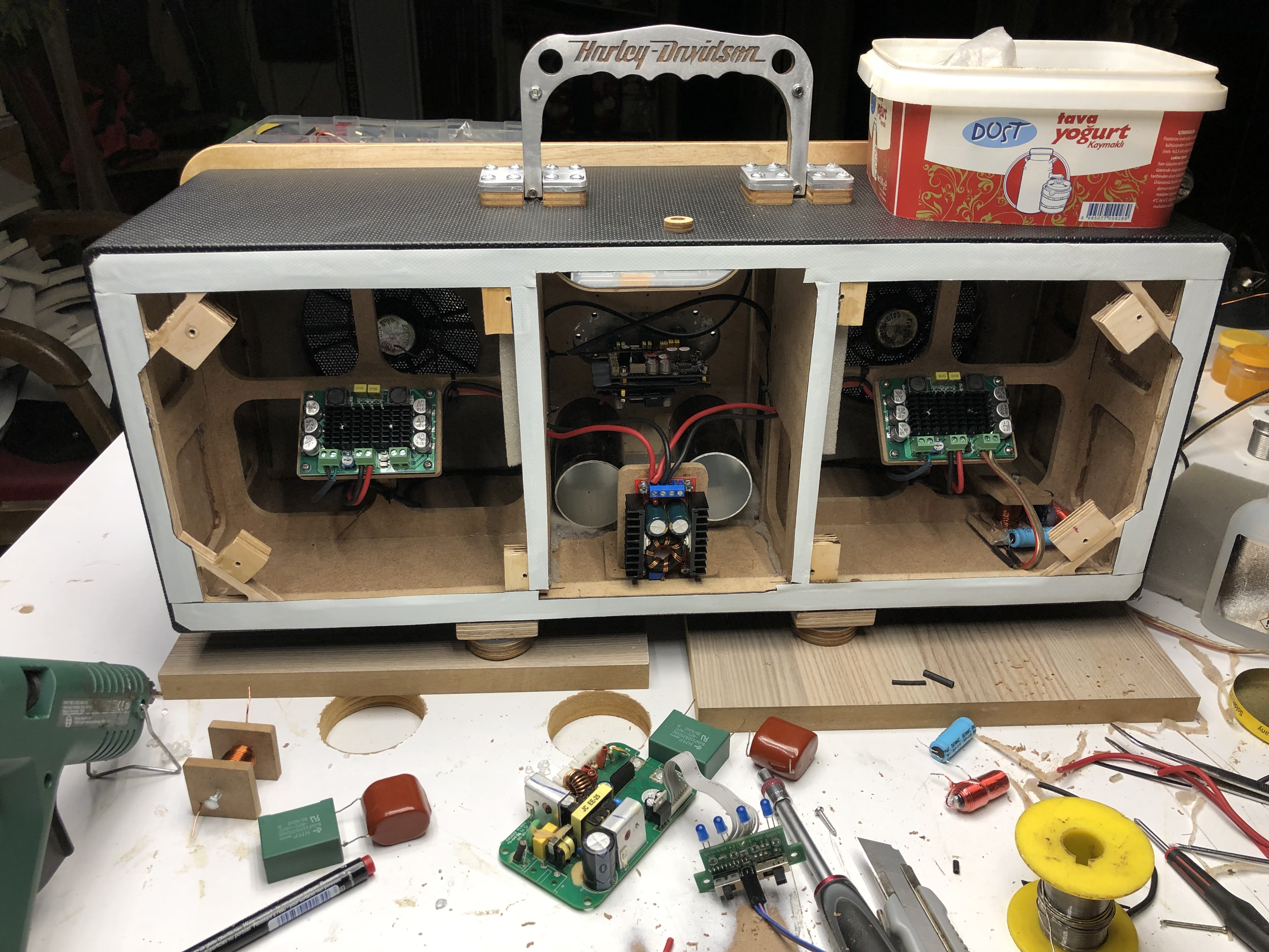
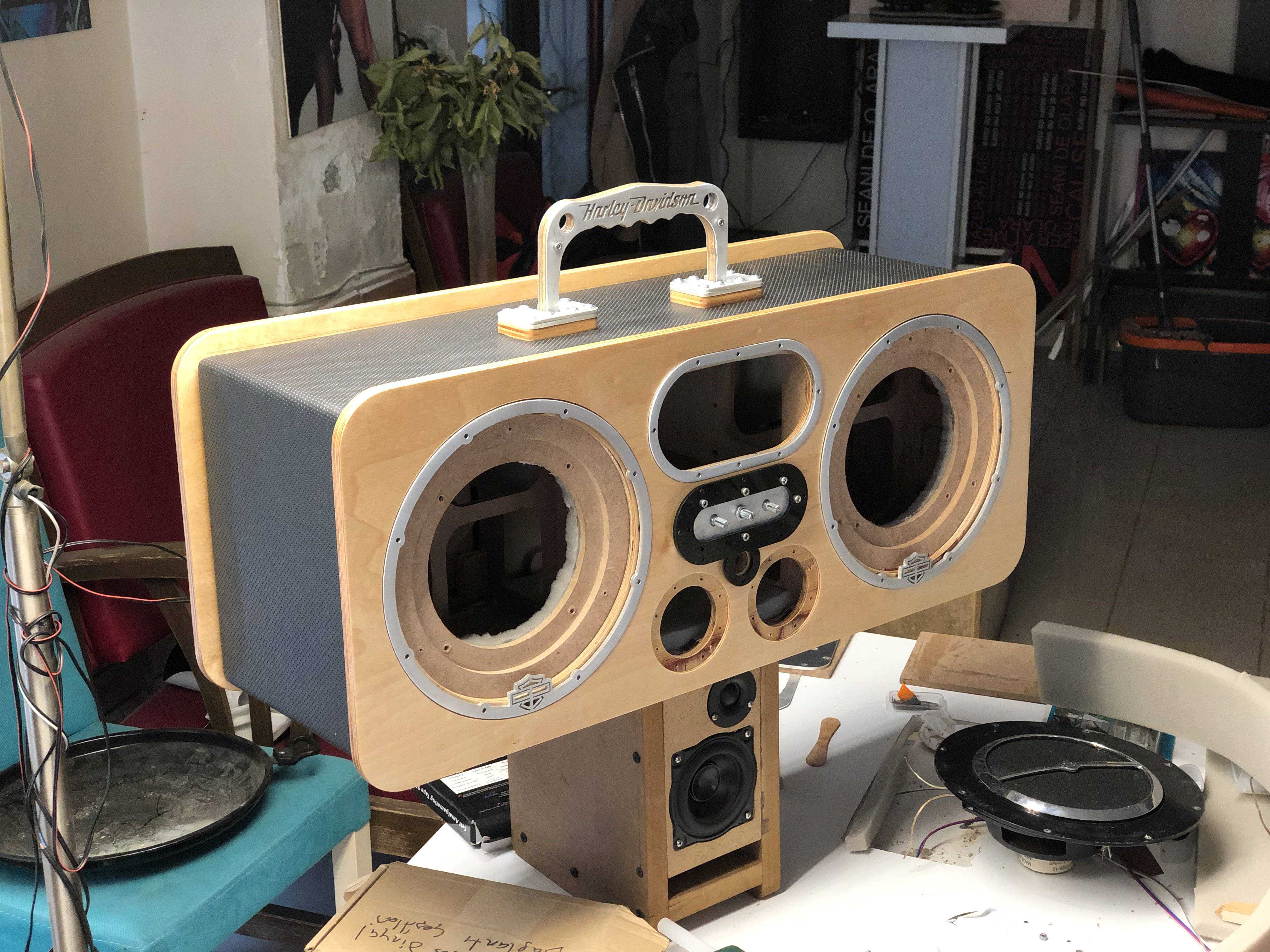
There is a cover, but I'm working on adding some vents to it so it's running open now. Chips and their radiators get only slightly warm on my normal listening levels so I'll hold off on taking the whole thing apart to add vents on the bottom. After a couple teardowns for troubleshooting and repairs I want to finally use it for a bit, next build is where I'll step up my cooling.
@Carlp
I can keep my hand on it indefinitely, I guess I'm goodish. Thanks")
There is a cover, but I'm working on adding some vents to it so it's running open now. Chips and their radiators get only slightly warm on my normal listening levels so I'll hold off on taking the whole thing apart to add vents on the bottom. After a couple teardowns for troubleshooting and repairs I want to finally use it for a bit, next build is where I'll step up my cooling.
@Carlp
I can keep my hand on it indefinitely, I guess I'm goodish. Thanks
Designed a simple stereo chipamp for Tda1875, tda2050 etc
Just ordered the rest of the components.
All components soldered, will try it out soon
Attachments
Here are a couple of pics of a childhood dream I made(built) into a reality though I don’t think it was an audio system at time but close enough. Two LM3886 mono blocks powered by a 25v 200va toroidal transformer each and a 6j1/6j2/6k4(it has a few options) tube preamplifier. Nothing fancy really on the inside. I did swap out the capacitors on the board with Panasonic FC’s and the preamplifier board is one i got on AliExpress and took a chance with. The chassis’s I made with a couple of 12x12” aluminum sheets and a couple perforated ones. All in all I very pleased with it(sound wise)and a very proud of myself especially for a first go at building anything audio besides cables.
Attachments

Very nice.
I've made the same mistake myself many times...
Red RCA's are on the left side.
Yes, I use a boating term. " Is there any RED port left" learnt that from nice Scotsman.
for the boat, red light on the left/port side
for RCA, RED left.
To the opposite, Right red & Left blue Headphones
From observing the nice layout photos, I'm a little surprised that mains IEC filter sockets or/and AC mains snubbers are not commonly used. It there a reason with the constructors or you didn't know the benefits of muffling any noisy AC mains at first point of coming in?
@SRMcGee
I looked at the first picture without reading your post and thought "wow, there's a lot going on here", and then I clicked on the other pictures...
I also looked up the attenuator you're using and it's way more expensive than my entire amp
A more general question to people here: how warm should a transformer get? I know mine is undersized for the stereo LM1875 (2x16V 2A) but I mostly run it pretty quiet, still, after a couple hours it's toasty.
I have an overkill toroid on the way so it's just my curiosity.
Nice build. Got a link to the brds.
More information on the project can be found here: https://www.diyaudio.com/community/threads/lm3886dr-dac-build.380135/
Short summary:
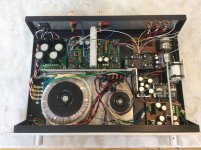
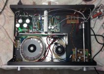
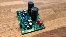
Some time ago, I started with a project, that got a bit out of hand. In the background, I'm still working on it, but with all the new ideas for that amp, the pile of unused components started growing: chassis, PSU boards + caps, transformer, DAC and volume control. So why not use those parts and make an amplifier out of it?
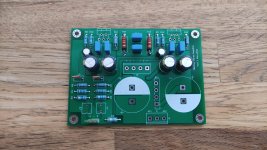
For this project I opted for the Neurochrome LM3886DR boards.
Short summary:
Some time ago, I started with a project, that got a bit out of hand. In the background, I'm still working on it, but with all the new ideas for that amp, the pile of unused components started growing: chassis, PSU boards + caps, transformer, DAC and volume control. So why not use those parts and make an amplifier out of it?
For this project I opted for the Neurochrome LM3886DR boards.
Attachments
Are those big blue caps you used on lm3886DR boards the only filtering caps of your amp?More information on the project can be found here: https://www.diyaudio.com/community/threads/lm3886dr-dac-build.380135/
Short summary:
Some time ago, I started with a project, that got a bit out of hand. In the background, I'm still working on it, but with all the new ideas for that amp, the pile of unused components started growing: chassis, PSU boards + caps, transformer, DAC and volume control. So why not use those parts and make an amplifier out of it?
For this project I opted for the Neurochrome LM3886DR boards.
Are those big blue caps you used on lm3886DR boards the only filtering caps of your amp?
Here you will find some more details on the PSU / rectifier / filtering caps, including pictures: https://www.diyaudio.com/community/threads/lm3886dr-dac-build.380135/#post-6877514
The filtering caps (4x 22.000uF/50V) are mounted on the bottom side of the PSU boards.
- Home
- Amplifiers
- Chip Amps
- Chip Amp Photo Gallery