dear all,
the thread is starting for vgitngc project assembly & developent.
project antetype below:
T-network: the better feedback solution?
Projects for next hollidays (the world smallest VBITNGC??)
pcb boards set group order below:
VBITNGC group buy
Zang
the thread is starting for vgitngc project assembly & developent.
project antetype below:
T-network: the better feedback solution?
Projects for next hollidays (the world smallest VBITNGC??)
pcb boards set group order below:
VBITNGC group buy
Zang
step by step assembly with photos.
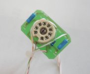
the vbitngc has 3 units.the first assembly is tube buffer unit.
Part list below:
Tube PCB *1
E88CC*1
10K 2W*2
3.3K 0.4W*2
1uf 200V mkp *2 *
the sch of tube buffer and amp
**
the tube that I used is 6922.the coupling caps is 2 ero 0.47uf160v connected in parallel per channel.
the source of suitable tube sockets:
http://www.diyaudio.com/forums/showthread.php?postid=758149#post758149
http://www.diyaudio.com/forums/showthread.php?postid=758154#post758154
thanks dave
Attachments


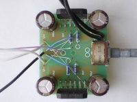
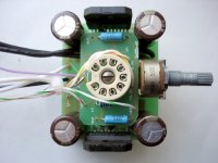
the second assembly is amp unit.
The parts for the amps board were printed by their value on the boards.
Part list below:
AMP PCB *1
LM3875TF *2
50K log Poti stereo *1
330uF / 35V low ESR *4
180R 0.4W 1% *2
18K 0.4W 1% *6
47K 0.4W 1% *2
**
the bypass caps that I used is Fc 100uf/35V.
The parts for the amps board were printed by their value on the boards.
Part list below:
AMP PCB *1
LM3875TF *2
50K log Poti stereo *1
330uF / 35V low ESR *4
180R 0.4W 1% *2
18K 0.4W 1% *6
47K 0.4W 1% *2
**
the bypass caps that I used is Fc 100uf/35V.
Attachments

I am waiting for a cad drawing from my supplier and an offer for ready prepared boxes.
As soon as I get the drawing, I will post it here.
On the other hand, it should be quite easy to build the own case out of two aluminium sheets.
Franz
As soon as I get the drawing, I will post it here.
On the other hand, it should be quite easy to build the own case out of two aluminium sheets.
Franz
Zang, witch of the posted PSU schematics can be used? There are different types on the forum. I assume the one from Franz d.d. 6 oktober 2005 is de right one?
And why in the BOM 2 trafo's from 2x18 VAC?
Can we see pictures from a build PSU too?
And why in the BOM 2 trafo's from 2x18 VAC?
Can we see pictures from a build PSU too?
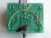
There seems to be an error in the silkscreen of the PSU board.
I suspect D1,D2,D3 to be printed the wrong way. I don't see this work as a proper bridge as it is drawn at the moment...
I suspect D1,D2,D3 to be printed the wrong way. I don't see this work as a proper bridge as it is drawn at the moment...
I still can't wait to get my hands on one of these, the only valve driven item I have is an old valve radio my grandfather build. Although I know the valve sound from band equipment like Fender bass amps etc... vely nice
Got my boards today, they seem to be well done.
Maybe the holes for the tube socket could have been bigger. I had a hard time fitting mine into them.
Will inform of the progress.
Cheers
Andrea
Maybe the holes for the tube socket could have been bigger. I had a hard time fitting mine into them.
Will inform of the progress.
Cheers
Andrea
I used a drill to make the them slightly larger. There are more holes which weren't as expected. I had to bend the leads of my Elna duorex to make them fit the PSU board.
I had the same problems, fitting the tubesocket on the PCB.
Hanzwillem, strange there is no comment on your post about the wrong PS PCB layout. I posted some other questions, but received also no answers.
Are Franz and Zang together on a lazy hollyday😉
Hanzwillem, strange there is no comment on your post about the wrong PS PCB layout. I posted some other questions, but received also no answers.
Are Franz and Zang together on a lazy hollyday😉
Sorry, I spend my weekend with my little daughter. Just in a hurry:
It seems in fact to be a mistake in the silk screen of the psu board. So, think about a correct bridge topology, before you solder the diodes!
I think, "my" schematic and the schematic from Zang are adequate. Two corrections: the filament voltage is +6.3VDC and ground (not -6.3VDC) and the 85VAC are too high to use with 63V electrolytics.
http://www.diyaudio.com/forums/showthread.php?postid=753303#post753303
About the tranny:
You could use one, two or three trannies. Important is to have:
- 2 x 20VAC about 165VA (you are free to do your own gain calculation, depending on the available tranny as mentionned in the LM3875 datasheet)
- 6 to 8VAC 10VA (filament 6.3VDC and NE555/relay circuit)
- 35 to 45VAC 5VA min (anode voltage)
Franz
BTW:
Nice PSU simulation, to simulate the available trannies: Search for Duncans Amp Tools, PSU simulator. It is free.
- Status
- Not open for further replies.
- Home
- Amplifiers
- Chip Amps
- VBITNGC building & comment