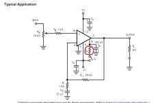
Pin 4 is the negative supply and so should have your negative 28 volts present.
Pin 8 is the mute pin and should as mentioned earlier be configured in accordance with the recommended components. As a minimum pin 8 should connect to pin 4 via a resistor the value of which is chosen to allow at least 0.5 milliamps to flow. This disables the mute.
I don't know how the LM3886 handles a direct connection there and what sort of current may flow. I suspect the chip will be OK (as in not damaged) but it definitely isn't recommended.
Maybe others who have used the chip would be able to comment on whether it might have caused a problem.
When you switch on and if a speaker is connected at this time can you hear any noise or thump or anything at all from the speaker?
Attachments
I would have expected some kind of audible noise of some sort... which kind of suggests either a basic wiring issue or a problem with the mute pin.
I'm afraid I don't know whether a problem with the mute would allow any noise at all to be heard or not.
It is hard to know what to advise for the best here. If you do rehash things then please connect the mute pin as per the data sheet and not just directly to the negative supply.
I'm afraid I don't know whether a problem with the mute would allow any noise at all to be heard or not.
It is hard to know what to advise for the best here. If you do rehash things then please connect the mute pin as per the data sheet and not just directly to the negative supply.
If you have a super steady hand then you could measure and record all the DC voltages on all the pins of the chip and see if that gives us any clue at all but you would have to be very careful not to slip and short any. Measure from the main ground (between the big caps) and make sure to include polarity such as +3 or -28 etc.
Pin 1 =
Pin 2=
and so on.
Pin 1 =
Pin 2=
and so on.
I'm getting nothing, no thump or static or hum. This is really depressing. I don't want to give up, but I feel like starting again from scratch (but changing some things somehow). I have more of all of the components so I could do that?
I've done some very large projects and later found single connections missing.
Wondering why I was getting FM reception on just an amplifier. Pilot communications etc..
Pfft and smoke!
Long time ago
You will survive
It is odd though that it is silent from the speaker. Most amp problems at the very least cause hum, thumps, bangs... smoke  .
.
So for it to be totally silent is a bit weird.
Try the methodical voltage check and recording the results back here and I'll see if anything looks amiss but of course no guarantees. The devil is in the detail and we would be looking for little things that might point to a problem.
.So for it to be totally silent is a bit weird.
Try the methodical voltage check and recording the results back here and I'll see if anything looks amiss but of course no guarantees. The devil is in the detail and we would be looking for little things that might point to a problem.
Hello again, not given up yet! Here's what I have done to better understand the schematic. I've drawn my versions of both the power supply and the amp. Could someone look them both over and check that it does exactly the same thing as the original schematic please? Originals are here:https://www.instructables.com/Make-your-first-Serious-Amplifier/
These are my interpretations...


As you can see, I don't understand what goes on exactly with the potentiometer.
These are my interpretations...
As you can see, I don't understand what goes on exactly with the potentiometer.
Last edited:
So...
The pot is OK as drawn. The middle pin of the pot goes to the 1k as you have it. Ideally you should AC couple the 1k with a cap of say 4.7uF but it will all work as shown... at least the pot will The audio will feed into the top of the pot (you haven't shown a connection there) and ground.
There is an error with the speaker wiring coming from the chip. Can you see what it is?
The pot is OK as drawn. The middle pin of the pot goes to the 1k as you have it. Ideally you should AC couple the 1k with a cap of say 4.7uF but it will all work as shown... at least the pot will
The audio will feed into the top of the pot (you haven't shown a connection there) and ground.There is an error with the speaker wiring coming from the chip. Can you see what it is?
The speaker wouldn't have both connections? What I mean is, one would have the connection from pin 3, the other speaker connector would have the ground? I've only drawn one. Is that right?
As for the +25v supply, I thought I'd just copied what happens on the author's original sketch. Obviously not
As for the +25v supply, I thought I'd just copied what happens on the author's original sketch. Obviously not
Last edited:

That looks better.
If you build it like that then it should work. Once you have it in that basic working state then we can tweak the little things such as AC coupling the input and perhaps adding a coil in series with the speaker feed.
As it stands though it should work.
I'll look in later...
If you build it like that then it should work. Once you have it in that basic working state then we can tweak the little things such as AC coupling the input and perhaps adding a coil in series with the speaker feed.
As it stands though it should work.
I'll look in later...

- Home
- Amplifiers
- Chip Amps
- Complete novice alert! *don't read if easily annoyed by stupid questions*