As requested by aparatusonitus, I tried the LM3886 with the compensation recommended by Tom from Neurochrome.
Excellent, thank you again...SPiKe protection seems to be a bit aggressive and will do everything to protect the IC...so every effort should be made to prevent it from activating at all.
Image 6: 1KHz, signal level reduced to 48Vpp (24Vp) and waiting some 15 seconds.
This picture doesn't look like it should...more in the attached documents.
Attachments
The LM3886 has output transistors of not 150°C but 250°C . The datasheet provides minimum heat sink to function safely at 120°C Tj . The curves show on figure 8 in your first document,the ability to dissipate 40W 100ms at 75°C Tc before it activates spike protection. This is the secret of Gaincard amplifier with it's tiny enclosure, to make the IC function at high temperature. LM3886 singing at HELL°Excellent, thank you again...SPiKe protection seems to be a bit aggressive and will do everything to protect the IC...so every effort should be made to prevent it from activating at all.
This picture doesn't look like it should...more in the attached documents.
Last edited:
Many thanks to both of you for the further information.
The application note gives me the information, on pages 7 and 9, that the current limit indeed is 6A and it may decrease in value with time when activated. My estimation wasn't that bad.
The SPiKe protection system is indeed complex and may be efficient for protecting the chip.
My initial goal is to make an overview of the most common chip-amps that are easily used in a composite amplifier. For myself and other members with less chip-amp experience.
Mastering the LM3886 is not a trivial task, probably due to SPiKe. I will investigate further when I make my first real LM3886 stereo amplifier. Your information will be very handy then.
So the question is, who is the next test subject?
I'm currently finishing a "report" on the UTC-TDA2050. This short report is posted in the other thread. It is a very suited chip.
Then, I may redo a bit of TDA7293/LM3886 test results with different compensations (for this thread).
I am awaiting delivery of genuine LM1875 for test on the other thread. In the same delivery I get some OPA549T. That is a power OP-AMP designed for use down to unity gain. Perhaps less surprise but a question of if they are worth the higher price. Test results for this thread. Delivery time is questionable now with the corona-virus hampering most activities.
Then I guess it will be the TDA1514A with test results for this thread.
TDA7293
Having gained experience from the TDA2050 that the best compensation of instability at low closed-loop gain may be a simple resistor between the two input pins, I tried that option replacing the CR-string. Indeed, the square wave reproduction at 20KHz seemed somewhat better. As a drawback, the sensitivity to capacitive loading at the output seemed worse. Before, 100nF was about the limit for permanent oscillation at the output. After, around 10nF was found to be the limit. With a Thiele filter in-between the capacitive load and the TDA7293 output, even 1uF could be connected without causing permanent oscillation.
Three resistor values were tried between the two input pins – 470 Om, 560 Ohm and 680 Ohm.
The results are shown below for a gain of -5 times. I prefer the use of 560 Ohm as replacement for the CR-string.
Tests with +/-25V supply voltage and 4 Ohm load
Image 1: 20KHz, 20Vpp and 470 Ohm resistor.
Image 2: 20KHz, clipping at 43Vpp and 470 Ohm resistor.
Bandwidth measured to around 560KHz.
Image 3: 20KHz, 20Vpp and 560 Ohm resistor.
Image 4: 20KHz, clipping at 43Vpp and 560 Ohm resistor.
Bandwidth measured to around 600KHz.
Image 5: 20KHz, 20Vpp and 680 Ohm resistor.
Image 6: 20KHz, clipping at 43Vpp and 680 Ohm resistor.
Bandwidth measured to around 800KHz.
The current limiter showed once more a fully flat top without instability.
Attachments
-
 TDA7293_5x_20KHz_Clip43Vpp_4Ohm_680R.jpg247.9 KB · Views: 72
 -
 TDA7293_5x_20KHz_20Vpp_4Ohm_680RSQ.jpg166.6 KB · Views: 440
 -
 TDA7293_5x_20KHz_Clip43Vpp_4Ohm_560R.jpg241.9 KB · Views: 447
 -
 TDA7293_5x_20KHz_20Vpp_4Ohm_560RSQ.jpg194.4 KB · Views: 453
 -
 TDA7293_5x_20KHz_Clip43Vpp_4Ohm_470R.jpg279.9 KB · Views: 448
 -
 TDA7293_5x_20KHz_20Vpp_4Ohm_470RSQ.jpg149.3 KB · Views: 446
LM3886
Somewhat better results!
Following my stability experiments with the TDA2050 and subsequently the TDA7293, the time had come to try improving stability of the LM3886 with a single resistor replacing the CR-string.
With a gain of -5, I found the value of 470 Ohm to be about the best when looking at the square-wave response at 20KHz.
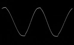
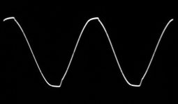
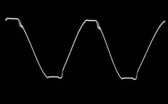
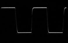
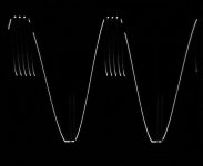
Tests with a regulated +/-25V power supply, a gain of -5 (1K/5K), and a 470 Ohm resistor between the two input pins.
Image 1: 20KHz square-wave at 20Vpp in a 4 Ohm load.
Image 2: 20KHz sine-wave and clipping at 43Vpp in a 4 Ohm load.
No signs of instability near clipping.
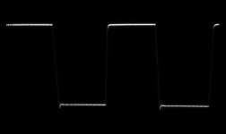
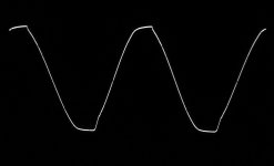
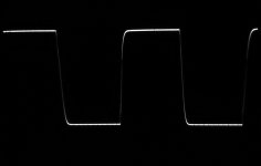
Then, repetition of the current limitation results that did not come out so pretty in posting #25.
The load impedance had to be reduced to 2 Ohm to be sure that current clipping would be reached.
I tried at both 20KHz and 1KHz. In both cases I had very little sudden oscillation from instability with that supply voltage. I had sine-wave peaks of 18V in 2 Ohm. Thus, peaks of 9A!, and quite regular clipping.
The datasheet speaks about a 135W “Peak Output Power capability”. It must be assumed to be in 4 Ohm. 135W in 4 Ohm means current peaks of 8.2A so it seems consistent.
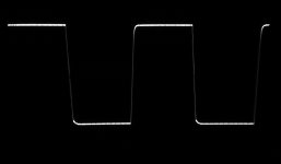
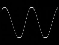
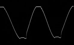
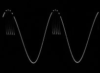
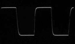
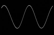
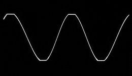
Image 3: 20KHz sine-wave current clipping at 36Vpp in a 2 Ohm load.
Image 4: 1KHz sine-wave current clipping at 36Vpp in a 2 Ohm load.
The sensitivity to capacitive loading of the output was also somewhat improved. With 10nF or 100nF at the output, there was no permanent oscillation but instability showed up at higher amplitude levels. A Thiele compensation network will still be needed.
With a 4Vpp sine-wave at the output, I measured the -3dB bandwidth to 400KHz. The output offset voltage was 16mV. Much better than for my TDA7293 (80-90mV).
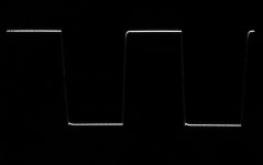
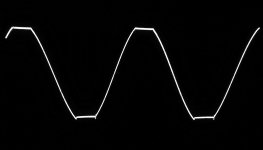
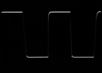
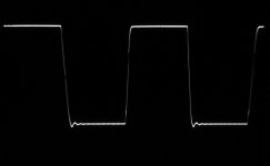
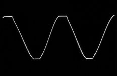
Finally I used my +/-35 V LLC SMPS as supply. The results were better than in posting #25 though some of the same instability as before reappeared. The load was 2.7 Ohm. The current limits reached were higher than before.
Instability started from 24-25V, corresponding to 9A, and the level stagnated at 28V equivalent to good 10A! The dynamic current capability of the LM3886 could be used. Instability at such high levels is less of a problem but indicates that the LM3886 should perhaps not be used at the top of the supply voltage range.
Image 5: 1KHz sine-wave, current clipping at 56Vpp in 2.7 Ohm.
I can only recommend to use a resistor of 470 Ohm across the input pins (and no CR-string) when using the LM3886 at a gain around -5.
Somewhat better results!
Following my stability experiments with the TDA2050 and subsequently the TDA7293, the time had come to try improving stability of the LM3886 with a single resistor replacing the CR-string.
With a gain of -5, I found the value of 470 Ohm to be about the best when looking at the square-wave response at 20KHz.
Tests with a regulated +/-25V power supply, a gain of -5 (1K/5K), and a 470 Ohm resistor between the two input pins.
Image 1: 20KHz square-wave at 20Vpp in a 4 Ohm load.
Image 2: 20KHz sine-wave and clipping at 43Vpp in a 4 Ohm load.
No signs of instability near clipping.
Then, repetition of the current limitation results that did not come out so pretty in posting #25.
The load impedance had to be reduced to 2 Ohm to be sure that current clipping would be reached.
I tried at both 20KHz and 1KHz. In both cases I had very little sudden oscillation from instability with that supply voltage. I had sine-wave peaks of 18V in 2 Ohm. Thus, peaks of 9A!, and quite regular clipping.
The datasheet speaks about a 135W “Peak Output Power capability”. It must be assumed to be in 4 Ohm. 135W in 4 Ohm means current peaks of 8.2A so it seems consistent.
Image 3: 20KHz sine-wave current clipping at 36Vpp in a 2 Ohm load.
Image 4: 1KHz sine-wave current clipping at 36Vpp in a 2 Ohm load.
The sensitivity to capacitive loading of the output was also somewhat improved. With 10nF or 100nF at the output, there was no permanent oscillation but instability showed up at higher amplitude levels. A Thiele compensation network will still be needed.
With a 4Vpp sine-wave at the output, I measured the -3dB bandwidth to 400KHz. The output offset voltage was 16mV. Much better than for my TDA7293 (80-90mV).
Finally I used my +/-35 V LLC SMPS as supply. The results were better than in posting #25 though some of the same instability as before reappeared. The load was 2.7 Ohm. The current limits reached were higher than before.
Instability started from 24-25V, corresponding to 9A, and the level stagnated at 28V equivalent to good 10A! The dynamic current capability of the LM3886 could be used. Instability at such high levels is less of a problem but indicates that the LM3886 should perhaps not be used at the top of the supply voltage range.
Image 5: 1KHz sine-wave, current clipping at 56Vpp in 2.7 Ohm.
I can only recommend to use a resistor of 470 Ohm across the input pins (and no CR-string) when using the LM3886 at a gain around -5.
Attachments
-
 LM3886_1KHz_CurClip56Vpp_470R_2.7Ohm.jpg244.1 KB · Views: 65
 -
 LM3886_5x_1KHz_CurClip36Vpp_470R_2Ohm.jpg220.3 KB · Views: 64
 -
 LM3886_5x_20KHz_CurClip36Vpp_470R_2Ohm.jpg203.6 KB · Views: 73
 -
 LM3886_5x_20KHz_Clip43Vpp_470R_4Ohm.jpg322.8 KB · Views: 71
 -
 LM3886_5x_20KHz_20Vpp_470R_4Ohm.jpg329.2 KB · Views: 73
TDA7265 / YD7265
TDA7265 is a good workhorse and available at an attractive price. It includes two channels that may be combined into a single channel with almost double the current capability of a single channel. TDA7265 is supplied in a housing with 11 pins such that it is reasonable to handle for DIY.
YD7265 is a clone of the TDA7265, made by Wuxi Yuoda Electronics in China. Often clones are manufactured as second source to a known brand name, such as Unisonic’s well performing UTC-TDA2050. Once when ordering a pair of TDA7265, I received two YD7265 instead. Somewhat disappointed I concluded that this could be an opportunity to test how such a second source product would perform. Somewhere I had read that YD7265 could be a disappointment with initial defects or poor performance. So, for a start I tested my two specimens with an Ohm-meter and realized that for one of my two YD7265, one channel output was internally shorted to the positive supply pin. Thus, this defect item could be discarded right away. The other IC initially seemed to work and test results are shown in a following posting.
I would first test the TDA7265 from ST and then compare with results for the YD7265.
Both channels were individually tested while only photos for one channel were made if the results were alike. In the end, the two channels were combined into one using load balancing resistors.
An 8 Ohm load is easily handled by the TDA7265 such that I would perform most of my test with a 4 Ohm load. TDA7265 should have sufficient current capability (4.5A peak) to handle a 4 Ohm load just to the clipping limit with +/-22V supply.
Without first looking in the datasheet, I implemented my test-board with gains of -10 (inverting). Then, I realized that the minimum closed-loop gain was stated in the dataheet to 25 dB (18 times) for stability reasons. But, as both channels actually performed without instability with a gain of -10, I let -10 be the highest gain. I subsequently assessed performance at gains of -5 and -3.
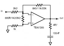
Image 1: Schematic with the essential components in the test board.
Tests with +/-22V regulated supply, -10 times gain, 8 Ohm load and no resistor between the input pins.
Image 2: 1KHz sine-wave with clipping at 40Vpp.
Image 3: 20KHz sine-wave with clipping at 40Vpp.
Tests with +/-22V regulated supply, -10 times gain, 4 Ohm load and no resistor between the input pins.
Image 4: 1KHz sine-wave at 24Vpp.
Image 5: 1KHz sine-wave with current limitation effects at 35Vpp.
Image 6: 20KHz square-wave at 20Vpp.
Both channels showed similar results.
As seen in Image 5, current limiting effects would start at the positive half-wave around 15V with a 4 Ohm load. For the negative half-wave around 17V. 15V across 4 Ohm means 3.75A. 17V across 4 Ohm means 4.25A. The current limiting effects look like short-lasting attempts to switch off the output current and then short after allow the output current for a brief moment. That type of signal can be expected to cause an unpleasant distorted sound. The 4.5A specified in the datasheet as typical current limit seems not to be realistic and I would not rely on an output current above 3.5A from a single channel. Luckily, the two channels can be combined.
A resistor between the two input pins would reduce ringing with a square-wave at 20KHz.
Image 7: Gain -10. 20KHz square-wave at 20Vpp with 2.2 KOhm between the input pins.
Image 8: Gain -5. 20KHz square-wave at 20Vpp with 1.2 KOhm between the input pins.
Image 9: Gain -3. 20KHz square-wave at 20Vpp with 680 Ohm between the input pins.
Similar to what was found for other chip-amps, a well chosen resistor between the two input pins will leave a well damped square-wave response.
The sensitivity to capacitance connected directly at the output was checked with a gain of -3.
10nF was handled without instability. From 68nF a bit of instability could appear and 100nF appeared to be about the limit where more severe instability would be seen.
The bandwidth was measured to 290KHz at 4Vpp amplitude, in 4 Ohm and with a gain of -3.
The two outputs from the two channels were combined into a single output using two 0.25 Ohm load-balancing power resistors. The combined output should be able to supply 7A of peak current. The load had to be reduced to 2 Ohm for allowing such current values.
Image 10: Gain -3. The two channels combined. 1KHz and 2 Ohm load impedance.
Image 10 shows the output curve with an amplitude around 30Vpp in a 2Ohm load, Current limit effects are seen from just below 13V. 12V is still “safe”. 12V in 2 Ohm means 6A. 6A was below what I had expected but still sufficient to ensure no such current limiting effects in a 4 Ohm load.
The sensitivity to capacitance connected directly at the output was checked with a gain of -3. With parallel-coupling of the two TDA7265 channels, 100nF was handled without any signs of instability. Even 1uF at the output caused only minor oscillation on the output signal from time-to-time.
The bandwidth remained 290KHz with 4 Vpp in 4 Ohm.
While the TDA7265 has many attractive characteristics for a moderately powerful amplifier, operation with current limitation is a drawback. When using the two TDA7265 channels in parallel, current limitation should not be invoked as 6A is not reached.
A following posting will show comparative results of the YD7265.
TDA7265 is a good workhorse and available at an attractive price. It includes two channels that may be combined into a single channel with almost double the current capability of a single channel. TDA7265 is supplied in a housing with 11 pins such that it is reasonable to handle for DIY.
YD7265 is a clone of the TDA7265, made by Wuxi Yuoda Electronics in China. Often clones are manufactured as second source to a known brand name, such as Unisonic’s well performing UTC-TDA2050. Once when ordering a pair of TDA7265, I received two YD7265 instead. Somewhat disappointed I concluded that this could be an opportunity to test how such a second source product would perform. Somewhere I had read that YD7265 could be a disappointment with initial defects or poor performance. So, for a start I tested my two specimens with an Ohm-meter and realized that for one of my two YD7265, one channel output was internally shorted to the positive supply pin. Thus, this defect item could be discarded right away. The other IC initially seemed to work and test results are shown in a following posting.
I would first test the TDA7265 from ST and then compare with results for the YD7265.
Both channels were individually tested while only photos for one channel were made if the results were alike. In the end, the two channels were combined into one using load balancing resistors.
An 8 Ohm load is easily handled by the TDA7265 such that I would perform most of my test with a 4 Ohm load. TDA7265 should have sufficient current capability (4.5A peak) to handle a 4 Ohm load just to the clipping limit with +/-22V supply.
Without first looking in the datasheet, I implemented my test-board with gains of -10 (inverting). Then, I realized that the minimum closed-loop gain was stated in the dataheet to 25 dB (18 times) for stability reasons. But, as both channels actually performed without instability with a gain of -10, I let -10 be the highest gain. I subsequently assessed performance at gains of -5 and -3.
Image 1: Schematic with the essential components in the test board.
Tests with +/-22V regulated supply, -10 times gain, 8 Ohm load and no resistor between the input pins.
Image 2: 1KHz sine-wave with clipping at 40Vpp.
Image 3: 20KHz sine-wave with clipping at 40Vpp.
Tests with +/-22V regulated supply, -10 times gain, 4 Ohm load and no resistor between the input pins.
Image 4: 1KHz sine-wave at 24Vpp.
Image 5: 1KHz sine-wave with current limitation effects at 35Vpp.
Image 6: 20KHz square-wave at 20Vpp.
Both channels showed similar results.
As seen in Image 5, current limiting effects would start at the positive half-wave around 15V with a 4 Ohm load. For the negative half-wave around 17V. 15V across 4 Ohm means 3.75A. 17V across 4 Ohm means 4.25A. The current limiting effects look like short-lasting attempts to switch off the output current and then short after allow the output current for a brief moment. That type of signal can be expected to cause an unpleasant distorted sound. The 4.5A specified in the datasheet as typical current limit seems not to be realistic and I would not rely on an output current above 3.5A from a single channel. Luckily, the two channels can be combined.
A resistor between the two input pins would reduce ringing with a square-wave at 20KHz.
Image 7: Gain -10. 20KHz square-wave at 20Vpp with 2.2 KOhm between the input pins.
Image 8: Gain -5. 20KHz square-wave at 20Vpp with 1.2 KOhm between the input pins.
Image 9: Gain -3. 20KHz square-wave at 20Vpp with 680 Ohm between the input pins.
Similar to what was found for other chip-amps, a well chosen resistor between the two input pins will leave a well damped square-wave response.
The sensitivity to capacitance connected directly at the output was checked with a gain of -3.
10nF was handled without instability. From 68nF a bit of instability could appear and 100nF appeared to be about the limit where more severe instability would be seen.
The bandwidth was measured to 290KHz at 4Vpp amplitude, in 4 Ohm and with a gain of -3.
The two outputs from the two channels were combined into a single output using two 0.25 Ohm load-balancing power resistors. The combined output should be able to supply 7A of peak current. The load had to be reduced to 2 Ohm for allowing such current values.
Image 10: Gain -3. The two channels combined. 1KHz and 2 Ohm load impedance.
Image 10 shows the output curve with an amplitude around 30Vpp in a 2Ohm load, Current limit effects are seen from just below 13V. 12V is still “safe”. 12V in 2 Ohm means 6A. 6A was below what I had expected but still sufficient to ensure no such current limiting effects in a 4 Ohm load.
The sensitivity to capacitance connected directly at the output was checked with a gain of -3. With parallel-coupling of the two TDA7265 channels, 100nF was handled without any signs of instability. Even 1uF at the output caused only minor oscillation on the output signal from time-to-time.
The bandwidth remained 290KHz with 4 Vpp in 4 Ohm.
While the TDA7265 has many attractive characteristics for a moderately powerful amplifier, operation with current limitation is a drawback. When using the two TDA7265 channels in parallel, current limitation should not be invoked as 6A is not reached.
A following posting will show comparative results of the YD7265.
Attachments
-
 TDA7265_3x_1KHz_30Vpp_2Ohm.jpg359 KB · Views: 84
 -
 TDA7265_20KHz_20Vpp_4Ohm_3x_680R.jpg214.4 KB · Views: 54
 -
 TDA7265_20KHz_20Vpp_4Ohm_5x_1K2.jpg267.6 KB · Views: 53
 -
 TDA7265_20KHz_20Vpp_4Ohm_10x_2K2.jpg390.7 KB · Views: 56
 -
 TDA7265_20KHz_20Vpp_4Ohm_10x.jpg374.9 KB · Views: 67
 -
 TDA7265_1KHz_CurClip35Vpp_4Ohm_10x.jpg326.6 KB · Views: 66
 -
 TDA7265_1KHz_24Vpp_4Ohm_10x.jpg269 KB · Views: 59
 -
 TDA7265_20KHz_Clip40Vpp_8Ohm_10x.jpg276.5 KB · Views: 64
 -
 TDA7265_1KHz_Clip40Vpp_8Ohm_10x.jpg289.1 KB · Views: 111
 -
 TDA7265_final.jpg20.9 KB · Views: 131
Hi FF,
your experiments with all these chip amps are really interesting and, as far as I know, unique.
Consider for a moment, that my personal opinion, " for an A/B amp, less than 200 Watt without distortion into 4 Ohm are the bare minimum for passive speakers", was a fact. (in reality this can sure be discussed).
If I look at these chip amps, at first sight there may be some low cost versions that seem attractive. Take a hand full, parallel them and bridge the whole thing. Done.
In real live, the first problem are the chips producers. Some versions are not available from a controlled production, some are even out of official production for years. Then, we have a whole lot of fakes on the market. If we parallel such low spec chips, we will in many cases see them blow up, as this idea is based on identical performers. If someone spent´s countless hours to build such an amp, I would not even start if the chip was not from TI, ST or another major player in the game. Saving €2.5 on a chip looks ridiculous compared to the projects total cost´s.
If we take into account, that we need a certain current for my 200 Watt amp, the whole thing gets problematic. A bridged 4 Ohm amp means two single ended 2 ohm stable sides. To be save, each side should be able to deliver a minimum of 20A, even 30A should not be unrealistic. Real live shows that a short at the output of an amp can not always be considered impossible.
To keep oscillations away, we should build a compact amp. It is near to impossible to build an amp from 20 single A/B chips and keep anything close together.
Some sort of matching circuit, may it be a servo or manual potentiometer, will be needed.
In the end my favorite candidate is the LM3886 for some reasons.
First, it is available at reputable suppliers, like Mouser, RS and the like. There, you can order it in packages of 20 for roughly €100. So you get 20 identical produced units, a good start for matching them.
2x3 pieces will give you well over 25A, even 34,5A if you trust the data sheet. Should make a tough amp.
3 chips per end can be kept quite compact, one should be able to adjust them with a simple pot. I do not see any advantage to use some complicated servo stuff.
The 3886 is considered a very well mannered product without mysterious problems. It can be build even without a PCB, with or without filters and will deliver. Other candidates have a history of blowing up even in reliable, tested designs, just because of some intolerant parts in the build.
It has been used powered by SMPS, a fact I find more and more interesting. If we build an amp that has quite some energy consumption, the idea to save on weight and heat by using a modern power supply is charming.
Last there are even some reasonable priced, PCB´s around, that seem to have a nice design. They may be copies of some high end mega buck amps, this is bad from a moral point of view. Technically, a good, stolen design is better than an independent one made wrong.
I spent quite some time and had a very close look at some, sometimes very pricey "commercial DIYS" products that fit my catalog of requirements.
To be honest, even as there are some impressive builds, they seem over engineered to me. Just because your are a gifted electronics designer, not any add on you can build makes an amp sound better.
Often less, but made right, seems to get results not worse than a million additional parts. Especially around a very good chip, let alone. As this might touch someones financial interests, I will not elaborate further.
This is a personal opinion and may not be suitable for anyone.
Last edited:
Hi Turbowatch,
I appreciate very much your unbeatable logic. Also your frank opinions and views. We are here to be challenged, not pampered.
There are two views to Audio DIY: that of putting together audio circuits which are at least as well performing as what you can reasonably buy and the other of knowing how to design audio circuits you find challenging.
For the first aim, there are many DIY constructions around even with PCB layouts. Making such a construction almost guarantees a good result without too much struggle. It will let you practice your soldering skills and your ability to make cabinet solutions. What may be less exercised is the understanding of the circuit being implemented.
I probably spend more time on making audio circuits than to listen to them. For me, it is rather about understanding the process than enjoying the result. A new result will soon follow anyway.
On this forum, most members may be interested in the final sound but I also know of other electronics freaks that need circuit challenges. We think of electronics as children of the Lego bricks – they leave large variations possible but a result is never kept for long before being taken apart and formed into something different.
Use of SMPS – I agree (often DIYers forget that they need a powerful power supply for a powerful amplifier). Use of good simple circuits rather than unexplainably complicated – I agree (sometimes a designer looses view on reality). “Steal” ideas (get “inspired” by others) – yes if necessary but try to look for your own solution first such that you understand why you “steal”.
For DIYers, class D soon becomes a bit restricted if you use a single chip. The gain can often be changed in steps and eventually also the carrier frequency but both leave rather predictable and minor differences. Else, you are bound to use a class D chip as it was intended. Building your own class D amplifier circuit from scratch is a challenge but probably too large a challenge for most DIYers. Designing your own solid-state (or vacuum tube) amplifier with discrete components is definitely a high-level challenge but clearly only for (very) experienced DIYers.
Building a class AB chip-amp amplifier as shown in the datasheet soon becomes too easy.
A good challenge for DIYers with medium experience is the composite amplifier. The power stages are simple and cheap but need to be kept under dynamic control (advises in this thread). The power stages can be combined in parallel or BTL in order to allow higher current handling and increase of output power until more hundred Watts. The pretty simple controlling OP-AMP circuit can be trimmed without more than an oscilloscope and a signal generator, and the THD results (and probably also sound quality) will beat most of what is commercially available.
I agree with you that the LM3886 is a very attractive candidate.
My tests of the LM3886 came out well in the end. I had to get some instability under control before I could use the more unique current capability (Dynamic Peak Power Capability) of the LM3886. I managed some 9A before instability appeared. I agree with you that it is one of the chip-amps with most potential but also one of those that change dynamic behavior with increasing supply voltage. One challenge is to keep the LM3886 under dynamic control, another to avoid the SPiKe protection to become active. Price-wise it is very reasonable for its high performance level.
Right, my purchases from Asia have sometimes shown that you are not sure what you get. However, a bit more than a week ago I ordered OPA549 from DigiKey.fr and they are not arrived either. Less trouble in Europe should be buying from reputed European suppliers but there are not many. Such as European electronic industry.
I had collected a number of chip-amps for experiments “on a rainy day”. “Rainy days” have come as all persons living in France are effectively put in house-confinement, except for when buying food or for medical visits and unless working in more essential jobs (I’m not). For a start during two weeks but it may be considerably longer.
So, I took my chip-amps and found ways to make them behave quite well. Mainly by applying a resistor between the two input pins. Then, other electronics freaks among the members than me can pick such power stages, combine them (parallel/BTL) if necessary and implement the controlling OP-AMP. I’m not certain that buying world-wide in the future will be as easy as until today. It is important that the choice of chip-amps is wide depending on what you can get your hands on at a fair price
Some will choose LM3886, other TDA7293 and many something less powerful like the TDA2050. All will have fun and a sound that is not much different from the high power versions.
YD7265
This is a short comparative test of the YD7265 as mentioned in posting #49. The test of my remaining YD7265 specimen was quick.
For a start I checked that the IC worked without load. Both channels did function but showed noise on the signal with an amplitude just below clipping. This noise resembled the spikes at current limitation of the TDA7265.
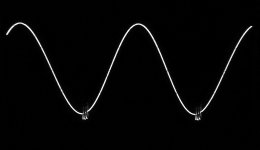
Image 1: 1KHz sine-wave at 36Vpp and without load. +/-22V regulated supply.
I tried to load the output with 4 Ohm but the output signal would collapse almost completely. Then I tried to load one of the channels with 8 Ohm to see if that was possible. The output signal would collapse less than with 4 Ohm but would be useless as an audio signal. While I was trying to adjust the amplitude of the collapsed signal such that I could make a photo, the chip made a worrying sound and started to smoke. The power supply went off.
The YD7265 had shorted power-pins and output pins to one another and the power supply fuse was blow to protect the power supply.
Removing the YD7265 from the board, I noticed that pins 3 (+ supply), 6 (- supply) 2 and 4 (outputs) had become one low-impedance connection. Unfortunately it had at the same time destroyed my previously functional TDA7265 on the same board.
Sometimes it is nice to draw an unambiguous conclusion: The YD7265, as assessed from two specimens, is absolutely useless. One was initially defect, the other was unable to supply a reasonable audio signal in just 8 Ohm.
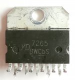
Image 2: The former YD7265.
Next, the TDA1514A.
This is a short comparative test of the YD7265 as mentioned in posting #49. The test of my remaining YD7265 specimen was quick.
For a start I checked that the IC worked without load. Both channels did function but showed noise on the signal with an amplitude just below clipping. This noise resembled the spikes at current limitation of the TDA7265.
Image 1: 1KHz sine-wave at 36Vpp and without load. +/-22V regulated supply.
I tried to load the output with 4 Ohm but the output signal would collapse almost completely. Then I tried to load one of the channels with 8 Ohm to see if that was possible. The output signal would collapse less than with 4 Ohm but would be useless as an audio signal. While I was trying to adjust the amplitude of the collapsed signal such that I could make a photo, the chip made a worrying sound and started to smoke. The power supply went off.
The YD7265 had shorted power-pins and output pins to one another and the power supply fuse was blow to protect the power supply.
Removing the YD7265 from the board, I noticed that pins 3 (+ supply), 6 (- supply) 2 and 4 (outputs) had become one low-impedance connection. Unfortunately it had at the same time destroyed my previously functional TDA7265 on the same board.
Sometimes it is nice to draw an unambiguous conclusion: The YD7265, as assessed from two specimens, is absolutely useless. One was initially defect, the other was unable to supply a reasonable audio signal in just 8 Ohm.
Image 2: The former YD7265.
Next, the TDA1514A.
Attachments
@FF
As always, I perfectly agree with you about the educational value of DIYS electronics and your technical view of the things under your microscope is very percise and interesting.
Now, please don´t get me wrong with my following words. It is just a hint, not questioning your fantastic work.
I think the only point where we disagree, is which material to choose for this task.
You are very tolerant to chips from unknown sources. That is where I see huge problems now.
If you have partners in science, you have to share the same material to work with. If you call a chip 7265, I do and Chris in Vienna, it should be the same part.
Otherwise, what you find out for your chip to work, will set my chip on fire and make the one Chris got from south east China or northern Timbuctu oscillate.
My approach is to find a good design, combine it with the necessary parts and make it work well. Then, I start again and refine and modify to make it better. If I do this with 3 different chips, all my work from one amp has nothing to do with the seconde one.
You have proven more than once, that there is no rule we can find in the chip market, other than "it is pure coincidence which chip we get". That makes me very uncomfortable. I don´t know how to get out of this dilemma.
Maybe we should learn, that if we go to a Chinese fish market, we may come home with a virus from a bat, instead of salmon chops and no one gives a damm as long as money is made. Same seems to apply for electronic components.
200W in 4 Ohm minimum
@Turbowatch2.
I took up your idea from postings #50 and #53 about the for you sufficient and for most of us ultimate class AB amplifier. 200W in 4 Ohm is just the limit of what 2+2 (parallel+BTL) UTC-TDA2050 can deliver, what 3 (parallel) TDA7293 can supply in SE mode with a +/-44V supply voltage or what 2+2 (parallel+BTL) LM3886 can provide with some margin. Having heated-up the soldering-iron anyway, make it 3*2 LM3886 and you have margins for both voltage and current.
TDA7293 has the advantage of being easy to connect in parallel, the LM3886 the advantage of being supplied in the insulated “TF” housing such that juggling around with insulating pads + insulating washers etc is avoided.
Three LM3886 in parallel can be made compact, in particular if each LM3886 is mounted on a separate module which is mounted perpendicular on a main-board with the controlling OP-AMP and the main power-lines decoupling capacitors on that main-board. While the three parallel LM3886 need to be pretty close together due to feedback to the adjacent controlling OP-AMP, two BTL channels can be further apart.
At a price of 6 Eur per LM3886, the costs are not scary for the ultimate thing and compared to the total project costs. I can follow your vision.
Soon I will present some test results for the TDA1514A. It is not meant to encourage members to start looking where to buy TDA1514A, which is no longer possible from reputed suppliers. Evidently as LM3886, TDA7293 and UTC-TDA2050 are available to most of the world, why look for a rare outdated product with no better performance? The reason why I find the TDA1514 important is that there are more persons like me who already have TDA1514A in their possession. And, parts of the world exist where taxes on import of LM3886/TDA7293 may be high. Asia is a part of the world with huge surplus stocks (and some fakes) and there an elderly TDA1514 may look attractive for Asians.
Where to buy is less clear. It could be with a group-purchase directly from TI. But buying in the US may add import taxes, expensive shipping and uncertain delivery (my experience is not the best). Advantages buying directly from TI are certainty of the chips being genuine and perhaps from the same production batch, as you write. A clear drawback with group-purchases are the not service-minded fees we will be charged for distribution to the individual participants.
My best buying experiences are from inside Europe (Reichelt, Conrad) where orders are normally delivered as expected. There are only few suppliers (TME.eu is a possibility as well). Would Reichelt do as supplier in your eyes?
Concluding on my experience with purchases from Asia, the issue clearly is “what do you get?”. I have received anything from what appears to be genuine (surplus stocks), new or recycled, fakes that mainly perform OK to scam-items that do not work at all. For experiments I can accept this uncertainty but if building a lasting construction, I would certainly appreciate being able to rely on the parts. Also as you say, having different results in different places would be a mess.
For me to see, it would be convenient if at least each LM3886 is put on (small) individual PCBs with identical layout such that member can use 1, 2, 4 or 6 of such modules per channel depending on the load impedance, the supply voltage and the maximum output power. Also such that repair of the power stage is on module basis. Repair of a power stage with parallel-coupled chips is difficult due to mutual interaction.
Low power connections may be through a connector but power rails and outputs should be high-current clamps in a way that each module can be removed and inserted separately.
A final question would be if there is enough interest in such a project? I believe there is already two composite amplifier threads on the forum using the LM3886. In the high-end there is further the Neurochrome products. I’m always ready to try “my way”, are others as well?
Last edited:
@FF, I think you are right in all you write. I will only comment on the suppliers. Conrad and Reichelt have a long history of selling fake parts and tearfull regretting it when you go public. A lot of their stuff is original, but as always in profit oriented companies, the margin is made in purchase, not resale. For one openly complaining customer, that speaks out on the net, there are multiple that don´t realize they got junk. To the seller this is just an inconvenience. If a customer insists, they will refund his money and sometimes even put him on the black list. For your project it may be the expensive out. There is not one of these mail order company´s, selling to end customers, which has a clean record. Also, as their stocks are limited, you often get different versions in an order if you buy more than one.
The simple way out of this problem, is to buy from a real distributors that sells to you if you order for more than €50. International sellers deliver with tax and custom service, so you have no surprise. Usually at 25 pieces of one item, good prices start.
Group buy seems complicated, but, if for example 3 members would combine one order, it is no problem to distribute a few chips in the EU, privately. Nice bonus would be, we could select the chips for groups of identical offset.
RS will charge €6.05 a piece to your EU doorstep, for an order of 40x LM3668TF. As 20 are one batch, they should be from one production, you can even notice this in the order and ask for two tubes from one run.
As 12 x LM3668TF should make a nice stereo amp, with maybe 2 chips as spare parts, costs are acceptable. Don´t forget we talk about a high end amp.
DigiKey will do it for 6 Cent more, Mouser maybe +9 Cent. So including private distribution, one should get away with less than €100 for the core parts.
Last edited:
I’m always ready to try “my way”, are others as well?
Yes, if this ends up in a board design, I will certainly want to order one. I like the idea of not using the LM3886 simply because the LM3886 is so heavily featured in DIY amp boards, something else could be interesting.
Am also very interested to see how the TDA1415A tests, simply because it sounds so good in my Linn Majik-I, I wonder how it will perform in your testing!
Hi FF + Turbo
I follow with interest your ideas and i am not really surprised that you plan such a high end amp. modular amp parts is a very good idea . a composite amp like the 1875 is for you not a problem.
sorry i do not want to push you but i really see FF´s triple 1875 module is working but to make a BTL-version i guess its a challenge especially if you plan to do it "modular".
yesterday night i thinking and searching around...
lm3386 module ?
DC+20 28V 68W LM3886 TF HIFI Power Amplifier Board PCB Parallel Bare Board|Instrument Parts & Accessories| | - AliExpress
the LM3886 (TDA7293, 7294) is about 6 euro at digikey. the only chip which is not as strong but cheaper is the TDA7295 - +/-22V 6Apeak ---> 3,36euro
for a high power amp i think you have to use TDA7293 or 7294 or LM3886
this is not really a genuine chip but this price is very interesting:
TZT TDA7293 Digital Audio Amplifier Board Mono Single Channel AC 12v 50V 100W|Integrated Circuits| | - AliExpress
just my 2 cents
chris
I follow with interest your ideas and i am not really surprised that you plan such a high end amp.
modular amp parts is a very good idea . a composite amp like the 1875 is for you not a problem.sorry i do not want to push you but i really see FF´s triple 1875 module is working but to make a BTL-version i guess its a challenge especially if you plan to do it "modular".
yesterday night i thinking and searching around...
lm3386 module ?
DC+20 28V 68W LM3886 TF HIFI Power Amplifier Board PCB Parallel Bare Board|Instrument Parts & Accessories| | - AliExpress
the LM3886 (TDA7293, 7294) is about 6 euro at digikey. the only chip which is not as strong but cheaper is the TDA7295 - +/-22V 6Apeak ---> 3,36euro
for a high power amp i think you have to use TDA7293 or 7294 or LM3886
this is not really a genuine chip but this price is very interesting:
TZT TDA7293 Digital Audio Amplifier Board Mono Single Channel AC 12v 50V 100W|Integrated Circuits| | - AliExpress
just my 2 cents
chris
@maxhifi
Do you, maybe, think of the TDA 7293?
It looks like the most obvious choice, and also has some advantages from a performance standpoint (i.e. higher voltage operation than LM3886)
Plus, the TDA7293 has been used in commercial high end amplifiers, like the Linn LK140, and the Linn Classik all in one system. I have not heard the LK140, but I found the Classik to be very nice sounding. I know the LM3886 has been used in some well received commercial designs too, but I think this gives both of these chips an edge.
Additionally, I couldn't agree more in principal that the availability of genuine parts is an issue too. The Philips TDA1514 is still interesting to me though, because it appears to be a high power bipolar transistor IC without any protection circuitry as severe as what the LM3886 uses. If it ends up offering any real advantages I'm not opposed to a treasure hunt.
Last edited:
It looks like the most obvious choice, and also has some advantages from a performance standpoint (i.e. higher voltage operation than LM3886)
yep, 120V are more then 94V........but look at the continuous power @4R load: (important for high current amps..i guess)
7293
Table 4 :+/- 29V---> 80W ---> d=1%
3886 Datasheet page 4
+/-28V ---> 60W ---> 0,1%
chris
- Status
- This old topic is closed. If you want to reopen this topic, contact a moderator using the "Report Post" button.
- Home
- Amplifiers
- Chip Amps
- Chip-amps suited as power stage in a composite amplifier, LM1875/TDA2050 excluded.