The 2U Dissipante is hard to beat. The BZ4309 from eBay is good too, but will probably cost more and take longer to arrive than the ModuShop Dissipante.
If you do go with the Dissipante, get the version with aluminum panels as the steel is rather hard to drill into. At least get the rear panel in aluminum.
Tom
If you do go with the Dissipante, get the version with aluminum panels as the steel is rather hard to drill into. At least get the rear panel in aluminum.
Tom
Historically -- i.e., back in the day when the TO-99 can was common, one didn't generally place the can flush with the board. Usually a little room was left. You could also buy little plastic spacers that did the job nicely. Google tells me someone is selling them on ebay.
Spacer or not, standard industry practice was to NOT mount the can flush to the board. First off, it risks solder bridging to the can. Secondly, it is nigh upon impossible to remove the can once soldered flush. If Tom's construction manual doesn't say this, it should!
As to Tom's repeated statement about the pin 8 indicator tab being odd: Metal cans with indicating tabs for semiconductors, either discrete or IC, were around long before other packages, so the TO-99 tab on pin 8 precedes any dual inline package. It would be an interesting historical investigation to determine how/why the standards became standard.
Actually, TI (or National) has thought of that already. The TO-99 from TI has a bump on the bottom to prevent the can from sitting flush with the board. It leaves about 1 mm of gap, thus eliminating the need for additional spacers.
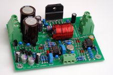
It's a bit hard to see, but you can make it out in the picture of the completed MOD86 Rev. 2.1 board (attached). It's also mentioned on the package drawing in the data sheet. They've thought of everything... Must be a National product. 😉
Tom
It's a bit hard to see, but you can make it out in the picture of the completed MOD86 Rev. 2.1 board (attached). It's also mentioned on the package drawing in the data sheet. They've thought of everything... Must be a National product. 😉
Tom
Attachments

I poked around a bit and found many pictures of TO-99 cans. All but one had the bump in the middle. I wonder if someone recognized the issue and fixed it once and for all.
At least I haven't had any issues with solder connecting to the can. Nor have I heard of any MOD86 builders who had that misfortune.
Of course, anything is possible if you apply enough solder. I did once bridge two pins on the THAT1200 by feeding too much solder into the joint.
Tom
At least I haven't had any issues with solder connecting to the can. Nor have I heard of any MOD86 builders who had that misfortune.
Of course, anything is possible if you apply enough solder. I did once bridge two pins on the THAT1200 by feeding too much solder into the joint.
Tom
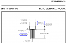
The "LMC" package designator on the drawing you show is the same package designator used on other TI/BB/NS can products. It's the non-hermetic can; the original (and likely more expensive) hermetic cans had a solid flat metal bottom much like TO-5 and other transistor cans of the era.
With the steel panels on the Dissipante I found drilling small holes was fine; for the larger ones I used a circular 24mm punch, which worked well (all my connectors were Neutrik, all 24mm hole with 2 x 3.2mm bolt holes. Would probably be a pain to make a rectangular cutout for an IEC socket unless you happen to have that particular specialist punch.
Hole punches are awesome. I wore out my stepped drill drilling into the steel panels of a ModuShop chassis. The drill generated enough heat to lift the powder coating as well. The end result was OK, but I'd much rather work in aluminum.
Alternatively, ModuShop will drill the holes for you for a very reasonable fee. From what I understand, the free Front Panel Designer software will spit out a file (.swg, I think) that ModuShop can use. QCAD would likely work as well.
Tom
Alternatively, ModuShop will drill the holes for you for a very reasonable fee. From what I understand, the free Front Panel Designer software will spit out a file (.swg, I think) that ModuShop can use. QCAD would likely work as well.
Tom
And the next step, connected the Modulus-86 units up to the power-86 one at a time and powered up with the light bulb thingy.. just like with the power-86 alone, bulb comes on and dims straight away. Could feel the LM3886's get warm very, very slowly.
So, all seems OK so far I presume.. now for the sound test...
So, all seems OK so far I presume.. now for the sound test...
Sounds good so far.
If the ±17 V supply checks out and the DC offset is near zero, your build is likely successful.
Tom
If the ±17 V supply checks out and the DC offset is near zero, your build is likely successful.
Tom
Build photos
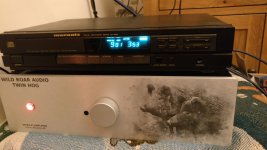
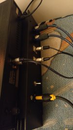
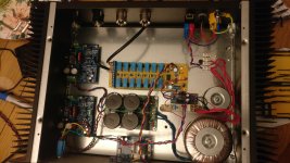
Right, I promised some photos of my build a while ago and finally here they are. I got my van Damme speaker cable today and made up my Neutrik to spade cables (when I build my next speaker project in a year or so I will use speaking on that too, and re-terminate the cables) so it's mostly complete. Only change still to be made is to replace the binary ladder relay attenuator, which doesn't provide enough attenuation at the quiet end, with one of Neutrality's logarithmic R-2R designs (see the thread elsewhere on diyAudio). I'm testing it with my Mission 750LE speakers and it sounds very, very good (listening to Led Zeppelin). Looking forward to cranking it up when the baby isn't sleeping....
I should add that the horrible plastic speaker in the third picture is the cheap sacrificial speaker for initial testing!!
Attachments

Last edited:
Dang! Nicely done! Props for using the Neutrik PowerCON connectors. The graphics on the front panel turned out rather nicely too.
Tom
Tom
🙂 thanks! The graphics were printed by the good folks at ModuShop. The absolute worst bit of the whole build was filing, by hand, a small square chunk of 3mm plastic IR window material into a round shape to exactly fit the hole just left of the volume knob. That was an absolute bear on my fingers! The Modulus-86s on the other hand were great to build.
Does the IR window material come in a rod? That would be convenient, albeit a bit late now. 🙂
Tom
Tom
Following our recent discussion here about the features that should be included in the Power-686, I'm finding myself mulling over the surge protector.
To provide the best protection, the surge protector needs to be selected according to the mains voltage. Also, as pointed out here, the surge protector should have a built-in thermal fuse, which then means there needs to be an LED to indicate protection status and the user needs to periodically check the LED to see if the equipment is still protected.
I doubt the surge protector actually does much. With 4x22000 uF capacitance, it'll take quite a surge to move the output voltage. Also, mains transformers are not exactly high bandwidth devices, so a fast pulse will likely not make it through the transformer. Thus, a surge protector will mostly just protect the auxiliary supply (SMPS). If the SMPS dies in a thunderstorm, it'll take an entire $5 to replace it.
While including a surge protector sounded like a good idea, it seems like a lot of hassle. A hassle that might be better left to an external $10 power strip with a surge protector built in.
Before I ditch the surge protector, I figured I'd ask if anyone of you is really passionate about having a surge protector included on the board. Would you prefer the PWR686 over another power supply if the PWR686 has a built-in surge protector?
Thanks,
Tom
Last edited:
If one wants to protect from line transients and surges, one should start in protection at the building's service entrance. Surge suppressing receptacles and /or power strips are also better. Proper surge protection should be line to ground as well as line to line. I agree with Tom. There may be some odd scenario in which the surge suppressor in the power amp would trigger. However, you really want to protect your entire SYSTEM and have the protection before any transient gets inside the amp chassis.
One can buy various genuine audiophile suppressors, but I've been happy with the Tripp Lite 'Isobar' series. These have transient protection as well as filters -- all the audiophile goodies without the hype and price.
One can buy various genuine audiophile suppressors, but I've been happy with the Tripp Lite 'Isobar' series. These have transient protection as well as filters -- all the audiophile goodies without the hype and price.
I think this kind of protection is better served by specific appliances. I'm using SPS SAFE - Salicru - Salicru - Multinational dedicated to the Electric Power | Stabilizers | UPS (7+) and quite happy
- Home
- Amplifiers
- Chip Amps
- Modulus-86 build thread