Wow Tom, my mental picture of you was at least 20 years older than you appear to be...makes your work that much more impressive!
So I come across as mature... I guess that's a good thing. 🙂 Thanks. I'm told I look younger than my age. I'm 42. You be the judge.
Tom
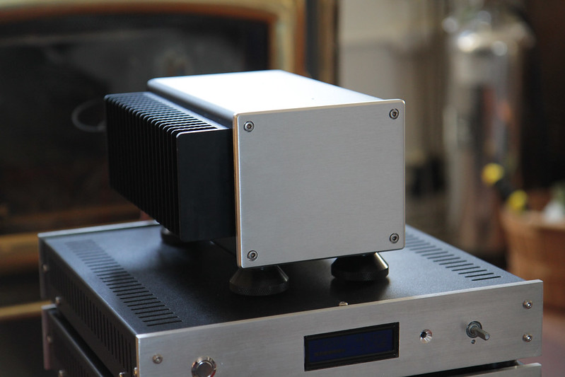
The initial casework for my mod-286 and SMPS 86 is now done. The unibody enclosure was challenging to work with, but I am satisfied with the result. I may do something with the front panel, but I am undecided for now.
 IMG_0499.jpg by PScal, on Flickr
 IMG_0508.jpg by PScal, on Flickr
 IMG_0519.jpg by PScal, on Flickr
IMG_0499.jpg by PScal, on FlickrIMG_0508.jpg by PScal, on FlickrIMG_0519.jpg by PScal, on FlickrDang! That's cool!! Nicely done.
The power ON LED is not mission critical. If you don't need it, just unplug it.
Tom
The power ON LED is not mission critical. If you don't need it, just unplug it.
Tom
So I come across as mature... I guess that's a good thing. 🙂 Thanks. I'm told I look younger than my age. I'm 42. You be the judge.
Tom
Whereas I just behave younger than my age 🙂. I think the one thing Tom and I have in common is neither of us has quite worked out what we want to go when we grow up!
I'm 42. You be the judge.
Tom
I'll be celebrating the 23rd anniversary of my 42nd birthday this year 🙄
Whereas I just behave younger than my age 🙂. I think the one thing Tom and I have in common is neither of us has quite worked out what we want to go when we grow up!
Easy: I just refuse to grow up.
Yeah... Life doesn't have to be linear.
Tom
...
Now that we're in the OT department, perhaps you fine folks could help me out a bit here. For my consumer psychology class, I'm doing a bit of marketing research. I decided to use Neurochrome for this; both to meet the project requirements and to get some data on how my company is perceived, where to take it from here, etc. I would greatly value the input from all of you and would greatly appreciate it if you'd spend 5-10 minutes taking my marketing survey: Neurochrome Marketing Survey. The survey is anonymous.
Tom
Done! I encourage others to do the same as it was a fun and easy survey.
Best,
Anand.
Just been surveyed and it is official... I need to be certified! 😉
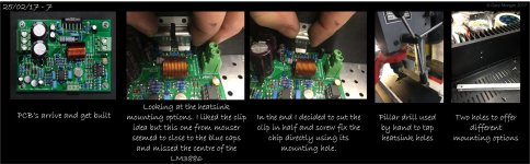
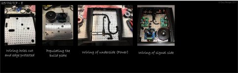
Attached are the latest storyboards from my build.
With the boards in hand, the need to make allowences for cables connections and against the best advice offered here I ended up with layout A. The XLR pin 1's are earthed at the rear chassis plate and the PWR-86 is bound to the mains protective earth at the bolt on the build plate need the mains inlet. I assume this is OK?
Attachments
Last edited:
Gary,
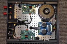
Awesome! One request. Can you post a big photo of your "signal wiring" pic?
Best,
Anand.
Awesome! One request. Can you post a big photo of your "signal wiring" pic?
Best,
Anand.
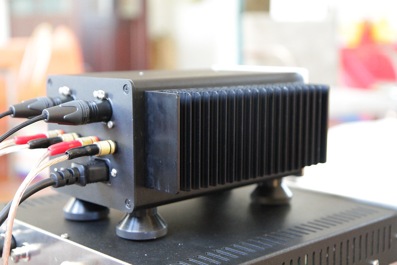
Cheers, would this do?
Tom, at 42 another of your offsping is born here in the UK!
Tom, at 42 another of your offsping is born here in the UK!
Attachments
Last edited:
The initial casework for my mod-286 and SMPS 86 is now done. The unibody enclosure was challenging to work with, but I am satisfied with the result. I may do something with the front panel, but I am undecided for now.
That looks great! Do you happen to have the dimensions of that enclosure handy (with/without the heatsink)? From the pics you posted, it looks impressively small. I'm a sucker for compact builds that manage to be so neat and tidy.
Again, great work and thanks for posting!
The case is a Mini Dissipante 2U (340mm wide by 300mm deep) purchased from here. They can even do the machining and engraving for you.
The case is a little crude in that the external scews are not countersunk (easily fixed) and corner brackets are unpainted and a bit sloppy.
I did not buy the internal plate (forgot) so ended up making one. If you were to purchase the case I'd recommend thinking about the internal plate.
I'm now wanting to make a preamp to go with it but I can't find a matching chassis size wise
The case is a Mini Dissipante 2U (340mm wide by 300mm deep) purchased from here. I'm now wanting to make a preamp to go with it but I can't find a matching chassis size wise
The chassis offered here are originally from modushop. They have Galaxy line which is ideal for preamp in 1U and 2U height. See for example this one. If you do not want the screws visible they have an option for this too (see the option at the left on the Galaxy chassis web page).
Dang! That's cool!! Nicely done.
The power ON LED is not mission critical. If you don't need it, just unplug it.
Tom
Thanks, Tom. It sounds great!
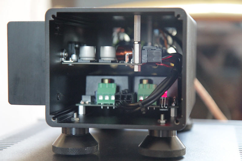
PScal, kudos on getting everything fitted within the space.
Thank you. A very specific assembly order was required. Many times, I wished my fingers were made out of spaghetti.
That looks great! Do you happen to have the dimensions of that enclosure handy (with/without the heatsink)? From the pics you posted, it looks impressively small. I'm a sucker for compact builds that manage to be so neat and tidy.
Again, great work and thanks for posting!
Thanks for the compliment. The case I used is this one, and the heatsink is from the DIY audio store.
Cheers, would this do?
Tom, at 42 another of your offsping is born here in the UK!
Cleanliness! Kudos! Enjoy the fruits of your labor!
Best,
Anand.
Gary, when you have a ferrous plate with wires passing through, you must be careful to ensure that both the Flow and Return of a pair pass through the same hole.Cheers, would this do?
Tom, at 42 another of your offsping is born here in the UK!
Gary, when you have a ferrous plate with wires passing through, you must be careful to ensure that both the Flow and Return of a pair pass through the same hole.
Thanks for your comments but how does it relate to my build? I know you cant see a lot in the story board pics but the whole chassis is Ali. The PSU connections drop through the plate to the bottom and pop back up at each amp. The wires +V, GND & -V have been tightly bound to each other (laced) and then covered in the braid.
Output protection & external mute control
Tom, I had a nasty incident today, somewhat self inflicted (source selection) 😱, but none the less got me thinking.
With the amp pratically finished it has been sitting on the side driving a pair or Alpair 7P's through thier 100 hour burn in. The source was a small DAB radio tuned to a classical station. Anyway we had a power cut. When the power returned the radio stuck DC into the amp and the cones shot forward 🙁. Luckily I was there to see it so pulled the plug quick. But it brings a new meaning to burn-in! The speakers seem OK only time will tell.
Anyway, I'm also considering my pre-amp options and I was thinking of externally muting the power amp via an opto coupler inline with the mute resistor. If I do this I could also provide some form of basic DC protection by monitoring the speaker O/Ps. I know this would not cater for a chip failure but it should allow for DC offset's given that the amp is DC coupled right?
- Home
- Amplifiers
- Chip Amps
- Modulus-86 build thread