Yeah, in your case with the 2xMOD286, it may make sense to get the 3U size of the Dissipante. Better thermals. More room. You could flip quite a few of the boards vertical then.
Tom
Believe me Tom, I've tried loads of combinations, including the use of a 3U case. It doesn't help that much with layout even if I vertically mount some of the boards and the 2U heatsinks at 0.45 C°/W should be fine shouldn't they?
Most importantly, I wouldn't get a full width 3U case past SWMBO!
Try using Figure 34. in the 3886 datasheet.
For a 70Vdc supply and 8ohms speaker National suggest a 3W/C sink for Ta=25°C
For two 3886 on a common sink they would recommend double (half) that, i.e. 1.5C/W
I always recommend you double the heatsink compared to what National show in Figure 34. That takes my recommendation down to 0.75C/W for dual 3886 driving 8 + 8ohms on ±35Vdc @ Ta=25°C
0.45C/W even way off centre easily meets the cooling requirements of the 3886.
Working back from 0.45C/W with my doubling, you would be looking at 1.8C/W for each 3886 and that allows about ±28Vdc driving 4ohms.
That keeps any 3886 chip cool enough that temperature de-rating of the Spike protection is hardly taking effect.
Last edited:
Hi Tom
I'll be first in line to buy a speaker protection board from you if you get round to designing one that dosen't compromise SQ.
In the meantime are you aware of any speaker protection designs out there that you could recommend?
Thanks
I'll be first in line to buy a speaker protection board from you if you get round to designing one that dosen't compromise SQ.
In the meantime are you aware of any speaker protection designs out there that you could recommend?
Thanks
I personally don't use speaker protection as the LM3886 is quite well protected as it is. But if it makes you sleep better at night, sure...
I should probably make a speaker protection board as there are some fairly easy way to muck up the performance if you do it wrong. The choice of relay matters greatly (as Doug Self writes about in his amp design book).
Tom
Thanks for that Andrew.
I also plan to use the non-isolated package together with some Keratherm 86/82
https://www.rapidonline.com/kerafol-keratherm-86-82-thermal-pads-6-5w-mk-gap-fill-sheets-high-power-537256
and, rather than tapping the heatsink, was going to use thread-forming TapTite screws.
I also plan to use the non-isolated package together with some Keratherm 86/82
https://www.rapidonline.com/kerafol-keratherm-86-82-thermal-pads-6-5w-mk-gap-fill-sheets-high-power-537256
and, rather than tapping the heatsink, was going to use thread-forming TapTite screws.
Hi Tom
I'll be first in line to buy a speaker protection board from you if you get round to designing one that dosen't compromise SQ.
In the meantime are you aware of any speaker protection designs out there that you could recommend?
Thanks
The company I was planning on buying a SoftStart board from do a speaker protection board:
Ochrany reproduktor? malé
I would be interested in any opinions on this.
If there are no big electrolytics blocking access i like to use clamps to secure the chipamps to the heatsink.
The little Tannoy active speakers use clamps on their twwo chipamps.
The little Tannoy active speakers use clamps on their twwo chipamps.
I'll be first in line to buy a speaker protection board from you if you get round to designing one that dosen't compromise SQ.
In the meantime are you aware of any speaker protection designs out there that you could recommend?
There are many speaker protection boards out there. I haven't tested any of them, so I can't make a recommendation. If I was going to point in any specific direction, I'd probably look at Rod Elliott's list of projects.
In addition to not compromising the sound quality, you also want a protection board that actually provides protection. Both of these requirements can be a challenge to meet at times. As far as the sound quality goes, the relay is the main tripping point.
Tom
Glad to see you finally building your Mod86s billshurv! You will smile when you hear them. Have fun and don't let the blue smoke out!
Rich
Rich
As far as the sound quality goes, the relay is the main tripping point.
Tom
Grounding schemes can also be an issue.
3000 posts. Over 300k page views. Nice work everybody! Cheers!
Tom

Oh carp, am I really that slow?
Pun intended?
Not exactly, though, I did notice it when I typed. 🙂
Grounding schemes can also be an issue.
True. There are also some optimizations one can perform by including the relay contacts within the feedback loop. That can cause trouble with pops on start-up, though, which defeats the purpose of a muting/protection relay for some.
Tom
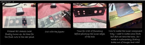
Here is todays update on the chassis build. The IEC inlet has turned up so I could complete the rear panel cuts.
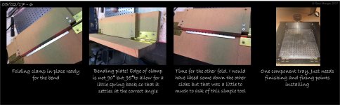
And I also got hold of some Ali plate so was able to make up the component tray. With that installed I can review the layouts again. More on that later.
And I also got hold of some Ali plate so was able to make up the component tray. With that installed I can review the layouts again. More on that later.
Attachments
... snip ...
For mounting the MOD86 boards in that chassis, I'd fashion an aluminum bracket that mounts to the heat sink and hits the mounting holes (with standoffs) on the MOD86 board. Alternatively, a mezzanine that clears the corner bracket for the chassis would solve it too.
... snip ...
Tom
Late to the party, but thought I'd add that I addressed that issue by turning down the two standoffs on the inside edge to get the board square to the heatsink surface. I do like the idea of the interior plate, though.
With the component tray fixed and the IEC inlet installed, time to review the layouts.
As per one of Tom's suggestions I extened the tray forward to allow for better transformer support if it gets mounted at the front.
Attached are the pictures of the layouts as opposed to the drawings.
A: This should result in a tidy build although the transformer position and heatsinking are not optimised. The primary transformer cables will need lengthening slightly but the secondaries can be shortened.
B: Again this should result in a tidy build with the advantage of keeping the PSU on one side of the chassis. But this time the issue is heatsinking with the two amps on one side.
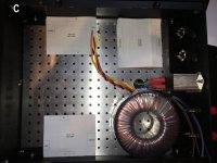
C: Should also offer a tidy build but all the amp input and output cables have to navigate past the PSU. Also the amps are located to one side of the heatsink
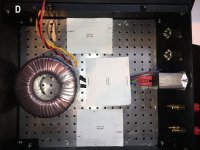
D: This not looking so good as there is very little space around the PSU PCB for cable management.
Need the PCBs to turn up so that I can build up and check the layouts for real.
In the meantime I'm trying to figure out the best way of making white labels for the panel legends?
As per one of Tom's suggestions I extened the tray forward to allow for better transformer support if it gets mounted at the front.
Attached are the pictures of the layouts as opposed to the drawings.
A: This should result in a tidy build although the transformer position and heatsinking are not optimised. The primary transformer cables will need lengthening slightly but the secondaries can be shortened.
B: Again this should result in a tidy build with the advantage of keeping the PSU on one side of the chassis. But this time the issue is heatsinking with the two amps on one side.
C: Should also offer a tidy build but all the amp input and output cables have to navigate past the PSU. Also the amps are located to one side of the heatsink
D: This not looking so good as there is very little space around the PSU PCB for cable management.
Need the PCBs to turn up so that I can build up and check the layouts for real.
In the meantime I'm trying to figure out the best way of making white labels for the panel legends?
Attachments


Last edited:
Do not paint the inner edges of the hole.Here is todays update on the chassis build. The IEC inlet has turned up so I could complete the rear panel cuts.
And I also got hold of some Ali plate so was able to make up the component tray. With that installed I can review the layouts again. More on that later.
To block interference entering via the LONG slot around the perimeter of the hole, the IEC can must make electrical contact with the plate that it passes through.
If there is intermittant electrical contact, then the length between contacts determines the minimum frequency that can pass through the slot.
You need to try to prevent corrosion building up between the steel can & plating and the aluminium so that the electrical contact is maintained over many years. I wonder if a copper laden grease would achieve this?
Do not paint the inner edges of the hole.
Rather stupidly I decided to mount the IEC from the rear to keep it all flush with the chassis for neatness. And the front of the socket is all plastic. So the paint was only for asthetics as I did not want to see the edges of the slot shining through. Doh.
The IEC socket's housing is Ali so there is no worry of corrosion. I guess I could apply some Ali or Copper tape around the edges of the socket. This would not show from the front but would maintain the sheilding. The physical connection to the plate is via the mounting screws and serated washers that grip the can.
I still have the option to mount the socket correctly, ie surface mount. It will mean I have to cut the panel a little larger.
I've done the same with the XLR's but as the bodies on them are all metal I assume that is not so much of an issue?
Attachments
![IMG_2533[1].jpg](/community/data/attachments/534/534458-274c4bc57a817e29ba60ade69956bd56.jpg?hash=J0xLxXqBfi)
![IMG_2534[1].jpg](/community/data/attachments/534/534489-f27e3603d58209e0244742a45d39d4c0.jpg?hash=8n42A9WCCe)
Gary, the power input module is designed to be mounted from the outside for goo connection to the chassis for a solid RF ground. I've not ever seen a piece of commercial equipment with the module mounted from the inside.
Any hole through an enclosure lets in interference.
Rather stupidly I decided to mount the IEC from the rear to keep it all flush with the chassis for neatness. And the front of the socket is all plastic. So the paint was only for asthetics as I did not want to see the edges of the slot shining through. Doh.
The IEC socket's housing is Ali so there is no worry of corrosion. I guess I could apply some Ali or Copper tape around the edges of the socket. This would not show from the front but would maintain the sheilding. The physical connection to the plate is via the mounting screws and serated washers that grip the can.
I still have the option to mount the socket correctly, ie surface mount. It will mean I have to cut the panel a little larger.
I've done the same with the XLR's but as the bodies on them are all metal I assume that is not so much of an issue?
The smaller the hole the higher the frequency that gets in.
A long slot is nearly as bad as a big hole with similar dimensions.
All the seams of an enclosure are effectively slots unless they are made to be electrically conductive along their length.
The hole for an XLR is that, a hole.
But if you fill that hole with a metal plug that is electrically connected to the sides of the hole, then RF can't get in.
The holes through the XLR are MUCH smaller than the hole for the socket. They will only let in frequencies about a decade higher and above.
If one were to assume that 3GHz is a reasonable frequency to give up trying to keep out, then the hole/slot dimension should be about 10% of that 3GHz wavelength. 3GHz has a wavelength of ~100mm. That fixes our maximum hole slot size at ~10mm.
Guess what? An RCA phono socket just needs a hole about 8mm to 11mm diameter, nicely proportioned for 3GHz.
Last edited:
Unfortunately most of the commercial gear I have seen mount the IEC and similar from the back. Most IEC cans have a nicely formed plastics recess designed to fit into a hole from the back. So nearly everyone uses that!Gary, the power input module is designed to be mounted from the outside for goo connection to the chassis for a solid RF ground. I've not ever seen a piece of commercial equipment with the module mounted from the inside.
XLR sockets are the same, mostly designed to be back fitted.
- Home
- Amplifiers
- Chip Amps
- Modulus-86 build thread