The trick is to deliver high power with Modulus-86 level performance. Few can do that.
That is for sure. Breaking the 1ppm barrier is no small feat. I was only commenting on the class-D vs AB aspect.
The PGP is a pretty good benchmark still today. But it's "only" 100W/8r, 200W/4r. Btw, syn08 has some interesting info on his website, especially wrt the output stage parasitics (at the bottom of the page).
I suggest: Make sure that the combined gain of multiple paralleled outputs and the baker clamps, will absolutely prevent driver push.I think I power have an advantage if they are well done, low distortion figures at high power definitely benefit audio playback. But as you get into higher power, you also get the drivers into the nonlinear region more often, thus you need to linearise large signal driver performance as a total system.
High power affects the quality of the Class D output inductors and that team is not habitually doing significant derating, so that the durability is a hazard. At this time it is not required to put one of those into a quality-first product catalog.Some of them were brought back, though. The LME49710, for example. Sadly not the LME49810/11/30. That's understandable, though. High power is class D these days, except for those of us crazy enough to fight the thermals of a Class AB design. The chips probably weren't selling. They were also in packages that weren't used by other products.
Tom
However, rather low current does also simplistically defeat that output inductor quality trouble, and it is also true that you don't have either a flea power or a Class D amplifier in your product lineup. Sure, I'll predict that the majority of Class D produce won't be able to meet your requirements. That doesn't mean it is impossible. It probably does mean that it will be a little one.
I suspect that you're probably working on a bigger scale discrete parts class Ab amplifier and I think that's a very good thing to do.
However, there are more garages, cheapskates, kitchens, dorms and little houses than there are airplane hangars. So, there is still that matter of the flea power amp for your lineup. Again, the low current usage defeats the output inductor quality trouble of Class D. Sure, it is also evident that most of that class is really bad crap done just because it is cheaper for heatsinks and power. But, the new news is that some of them are worthy at tiny scale. It wasn't likely to happen. But, it happened. Likewise, we should keep abreast of future developments. The majority won't be good, but one might be good. It could be that is a little one.
The PGP is a pretty good benchmark still today. But it's "only" 100W/8r, 200W/4r.
Nice! I also rather enjoyed how they eked every bit of performance out of their measurement setup (HP3562A) to measure the THD.
I plan to deliver better performance with maybe one tenth the parts.
Tom
Recently I noticed wiring can effect the inductance an amplifier sees, the normal twisted pair creates live and return path inductance that pretty much cancel each other, this makes me wonder about the direction of winding for the output inductor in the Modulus.
Sent from my iPhone using Tapatalk
Sent from my iPhone using Tapatalk
The inductance of the two wires in a twisted pair don't cancel. What this has to do with the output inductor in the Modulus-86 is beyond me. I'm not aware of an scientific argument that would indicate a preference for a specific winding direction of the output inductor.
Did you switch to the winter wardrobe? 😉
Tom
Did you switch to the winter wardrobe? 😉
Tom
I think what he meant is that:
A close coupled pair of Flow and Return wires has less inductance than a separated pair of Flow and Return wires.
It's easy to conclude that the inductances cancel, even though that conclusion is not technically correct.
There are Members and others who believe that resistors and capacitors have a preferred orientation to pass AC audio signals. They even believe that cable/wire orientation affects the final audio outcome !
Maybe that logic creeps into coiled wired as well?
Last edited:
The inductance of the two wires in a twisted pair don't cancel. What this has to do with the output inductor in the Modulus-86 is beyond me. I'm not aware of an scientific argument that would indicate a preference for a specific winding direction of the output inductor.
Did you switch to the winter wardrobe? 😉
Tom
I was actually surprised myself when doing speaker measurements not using twisted pair, but had to curl the cable through some stuff. I did actual measurements in different speaker windings. Since driver coil winding direction possibly could go either direction, this made me wonder. But you are right, twisted pair do not cancel out.
Sent from my iPhone using Tapatalk
Hi guys,
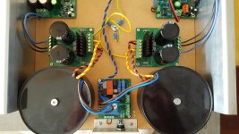
Going back OT with my build of a Parallel-86. Not many of these in this thread so i thought this might be a nice addition. First to introduce myself; tinkering with electronics since i was 10yrs old. I have been building all sorts of audio related equipment for the past 15yrs. Tube, solid state, amps, pre-amps, dac's, audio streamers etc. etc. Not only because i love music but also because i seem to find a zen like pleasure in building. Have owned all sorts of audio equipment from very expensive to very cheap depending on the monetary situation of my life 😉 Before ordering with Tom i had been reading about his work and design philosophy and got more and more curious. So when my last amp-project for a friend was finished i decided my next build was a Par-86.
As usual i first build/test the amp and ps boards and put the amp together in my regular mock-up. Its basically an MDF board with large heatsinks on the side, a hypex softstart and a backplane with power, se /xlr and speaker posts. Then things slowed down considerably and it's all Tom's fault 😛 Even in it's temporary form with shabby connections it sounded truly amazing and i just started listening to lots of records, alone and with audio friends. Finishing the build got paused for a while...
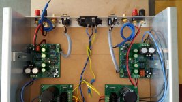
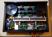
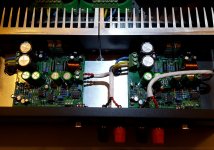
But eventually i had to put it into a case and finish with better/shorter cable connections etc. I used the well known galaxy enclosure from italy. Simple and clean. I use the additional perforated bottom plate. Most of the power wiring goes underneath to keep things neat and short. The sound quality hasn't changed a bit!
I'm not much of an audio reviewer but here goes anyway. First i integrated the amp into my current audio setup: Roon Audio streamer (diy) - DDDAC 1794 - RelaixedII preamp - Par-86 amp - JM Reynaud Bliss speakers. This turns out to be a match made in heaven. I cannot fault this combination in any way. I have a large music collection in flac format comprising of all sorts of genres, classical - jazz - soul - pop - metal - electronic. Using my usual set of test flac's this amp just does it's job without adding or leaving out anything. Bass is supertight, mids are fluent and engaging (female vocals are magic) highs are extended without being harsh. In short; a well balanced cohesive sound which reveals a lot without being analytical. I simply enjoy it, it puts my music front and center. What it's all about for me. This could honestly be my last amp without being sad about it. (my arcam is up for sale)
Currently the amp is on tour (i hope i get it back😉) with some of my friends who are all in love with it! Some of them own serious audio kit including Naim pre/power, Classe and Devialet. I guess it proves my point that most of the money you pay with the name brands goes into marketing and the bling-bling of the enclosure (milled from one piece of unobtainium blahblah). With the design Tom made it seems to be the opposite. I salute you and thanks.
Going back OT with my build of a Parallel-86. Not many of these in this thread so i thought this might be a nice addition. First to introduce myself; tinkering with electronics since i was 10yrs old. I have been building all sorts of audio related equipment for the past 15yrs. Tube, solid state, amps, pre-amps, dac's, audio streamers etc. etc. Not only because i love music but also because i seem to find a zen like pleasure in building. Have owned all sorts of audio equipment from very expensive to very cheap depending on the monetary situation of my life 😉 Before ordering with Tom i had been reading about his work and design philosophy and got more and more curious. So when my last amp-project for a friend was finished i decided my next build was a Par-86.
As usual i first build/test the amp and ps boards and put the amp together in my regular mock-up. Its basically an MDF board with large heatsinks on the side, a hypex softstart and a backplane with power, se /xlr and speaker posts. Then things slowed down considerably and it's all Tom's fault 😛 Even in it's temporary form with shabby connections it sounded truly amazing and i just started listening to lots of records, alone and with audio friends. Finishing the build got paused for a while...
But eventually i had to put it into a case and finish with better/shorter cable connections etc. I used the well known galaxy enclosure from italy. Simple and clean. I use the additional perforated bottom plate. Most of the power wiring goes underneath to keep things neat and short. The sound quality hasn't changed a bit!
I'm not much of an audio reviewer but here goes anyway. First i integrated the amp into my current audio setup: Roon Audio streamer (diy) - DDDAC 1794 - RelaixedII preamp - Par-86 amp - JM Reynaud Bliss speakers. This turns out to be a match made in heaven. I cannot fault this combination in any way. I have a large music collection in flac format comprising of all sorts of genres, classical - jazz - soul - pop - metal - electronic. Using my usual set of test flac's this amp just does it's job without adding or leaving out anything. Bass is supertight, mids are fluent and engaging (female vocals are magic) highs are extended without being harsh. In short; a well balanced cohesive sound which reveals a lot without being analytical. I simply enjoy it, it puts my music front and center. What it's all about for me. This could honestly be my last amp without being sad about it. (my arcam is up for sale)
Currently the amp is on tour (i hope i get it back😉) with some of my friends who are all in love with it! Some of them own serious audio kit including Naim pre/power, Classe and Devialet. I guess it proves my point that most of the money you pay with the name brands goes into marketing and the bling-bling of the enclosure (milled from one piece of unobtainium blahblah). With the design Tom made it seems to be the opposite. I salute you and thanks.
Attachments

😱 Fantastic build dude...wow...A++++
Kudos & enjoy the fruits of your labor . I use Tom's Modulus as a design reference for all my other builds
Best,
Anand.
Kudos & enjoy the fruits of your labor
. I use Tom's Modulus as a design reference for all my other builds Best,
Anand.
There are Members and others who believe that resistors and capacitors have a preferred orientation to pass AC audio signals. They even believe that cable/wire orientation affects the final audio outcome !
Maybe that logic creeps into coiled wired as well?
Could be. People believe the strangest things. It's been a while since I've posted a link to Mike Shermer's TED talk on the topic: Why people believe in weird things. 😀
In case of capacitors, there is some science behind the orientation of foil caps. Grounding the outer foil rather than the inner foil can make a (measurable) difference in EMI performance. If that matters in your application, buy caps where the pin connected to the outer foil is marked in some way (check the data sheet!)
I prefer a scientifically based approach. Others are free to disagree. 🙂
Tom
Going back OT with my build of a Parallel-86.
Thanks for the nudge. 🙂
But eventually i had to put it into a case and finish with better/shorter cable connections etc. I used the well known galaxy enclosure from italy. Simple and clean. I use the additional perforated bottom plate. Most of the power wiring goes underneath to keep things neat and short. The sound quality hasn't changed a bit!
That is a very nice build indeed.
This turns out to be a match made in heaven.
Very cool. I'm glad you like it.
I guess it proves my point that most of the money you pay with the name brands goes into marketing and the bling-bling of the enclosure (milled from one piece of unobtainium blahblah). With the design Tom made it seems to be the opposite. I salute you and thanks.
You're welcome. Thanks for sharing your build pictures.
Tom
I think what he meant is that:
A close coupled pair of Flow and Return wires has less inductance than a separated pair of Flow and Return wires.
It's easy to conclude that the inductances cancel, even though that conclusion is not technically correct.
There are Members and others who believe that resistors and capacitors have a preferred orientation to pass AC audio signals. They even believe that cable/wire orientation affects the final audio outcome !
Maybe that logic creeps into coiled wired as well?
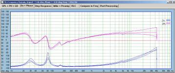
I have not really compared whether coiled cable in different direction are audible or not, only did measurements. When both hot and return leads are coiled in the same direction, the measured impedance amplitude and phase of the driver would change, either increase or decrease above a certain frequency; however, when each coiled in opposite directions, this will not happen.
Sent from my iPhone using Tapatalk
I happened to have some data with me, so I looked into some.Would you post a link to those measurements?
Tom
Three conditions for the speaker internal wire coiling, one with both live and return counter clockwise, one when both clockwise, and one with both coiled in opposite directions.
The enclosures have some different damping characteristics, but this was just a quick and dirty comparison as part of other efforts.
I don't recall any capability to simulate this in spice, but it would be interesting if possible.
Attachments
Last edited:
What you're describing would have enormous impact for RF engineers. No RF circuits would work if the wires coiled the wrong way. Are you sure you aren't chasing a ghost in your measurement setup?
20 dB difference at 20 kHz from the direction of a wire coil is absurd.
Tom
20 dB difference at 20 kHz from the direction of a wire coil is absurd.
Tom
You mean you had physically seperated wires (that is, not a twisted pair and close to zero mutual coupling) with arbitrary and unknown amount of coiling in each wire?Three conditions for the speaker internal wire coiling, one with both live and return counter clockwise, one when both clockwise, and one with both coiled in opposite directions.
I would suspect that all you found is that wires coiled up have inductance that depends on geometry. Unless you are controlling variables tightly (the exact geometry of both wire routings) no way you will see the same total inductance in repeated measurement.
Orientation of the corkscrew/coil pattern in each wire does not have any influence once this is the only variable, try it and you will see. Or course you should short out the driver (another point of getting rid of variables not needed for the subject of evaluation).
What you're describing would have enormous impact for RF engineers. No RF circuits would work if the wires coiled the wrong way. Are you sure you aren't chasing a ghost in your measurement setup?
20 dB difference at 20 kHz from the direction of a wire coil is absurd.
Tom
Those are impedance curves. I was surprised myself, that is why different directions were slipped in just to see what would happen. Which led me to wonder about amplifier output inductors.
Sent from my iPhone using Tapatalk
You mean you had physically seperated wires (that is, not a twisted pair and close to zero mutual coupling) with arbitrary and unknown amount of coiling in each wire?
I would suspect that all you found is that wires coiled up have inductance that depends on geometry. Unless you are controlling variables tightly (the exact geometry of both wire routings) no way you will see the same total inductance in repeated measurement.
Orientation of the corkscrew/coil pattern in each wire does not have any influence once this is the only variable, try it and you will see. Or course you should short out the driver (another point of getting rid of variables not needed for the subject of evaluation).
Not really intentionally controlled, but the number of turns on each side are the same, I would say the c-c distance between the corkscrews winding is around 120mm and the diameter of each would probably be 50mm. These are stiff wiring.
This was really not part of the original plan, but since it happened it just made me wonder. Maybe I will explore this more some other time.
Sent from my iPhone using Tapatalk
- Home
- Amplifiers
- Chip Amps
- Modulus-86 build thread