Tom did a very fine job with the parts mentioned. And they are available.
We should not be too hasty in modifying the design after he has made such an effort in fine tuning it.
Please build it straight on spec. Use the BOM.
It is only after that when you could make any sense if requesting something different you'd like it to do.
We should not be too hasty in modifying the design after he has made such an effort in fine tuning it.
Please build it straight on spec. Use the BOM.
It is only after that when you could make any sense if requesting something different you'd like it to do.
Tom how critical is the inductor value? I know the numbers might say 15 turns gives 2.2uH but my experience of winding them is home wound never come close to achieving the expected numbers
Last edited:
Cowanaudio,
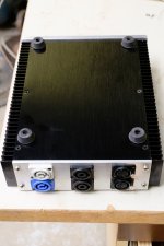
what are the bluish and whitish sockets for?
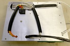
There are some single wires passing through holes in the interior mounting plate.
That is not good practice.
The Flow and Return of a current carrying pair should pass through the same hole.
You have some cable protected with double insulation except where they pass through metal panels.
The one layer of insulation would benefit from having a second layer through the holes. Not along the flat panels where there is little chance of abrasion.
What colour code does Australia use for the PE wire?
Change your white wire to that colour if it is your PE.
Last edited:
cowanaudio,
G'day!
Very neat and compact build you got there. Good work. 🙂
p.s. AndrewT has observations though!
G'day!
Very neat and compact build you got there. Good work. 🙂
p.s. AndrewT has observations though!
Last edited:
Cowanaudio,
what are the bluish and whitish sockets for?
There are some single wires passing through holes in the interior mounting plate.
That is not good practice.
The Flow and Return of a current carrying pair should pass through the same hole.
You have some cable protected with double insulation except where they pass through metal panels.
The one layer of insulation would benefit from having a second layer through the holes. Not along the flat panels where there is little chance of abrasion.
What colour code does Australia use for the PE wire?
Change your white wire to that colour if it is your PE.
The blue and grey connectors are Powercon, in and out. The out connector will be wired up once I finally receive the mains switch.
The temporary mains cables passing through the divider have a triple layer of insulation at that point. I was not so anal about the low voltage stuff. The single wires are only 20mm long before they meet their pair, where they are run in the same piece of heatshrink to the speaker connectors on the back panel. PE in Australia is green/yellow. I guess I should change that.
Tom did a very fine job with the parts mentioned. And they are available.
We should not be too hasty in modifying the design after he has made such an effort in fine tuning it.
Please build it straight on spec. Use the BOM.
It is only after that when you could make any sense if requesting something different you'd like it to do.
Daniel is absolutely right. No need to embellish or improvise.
Tom how critical is the inductor value? I know the numbers might say 15 turns gives 2.2uH but my experience of winding them is home wound never come close to achieving the expected numbers
sq225917,
I never had this issue, although I will admit that not ALL LCR meters are accurate, particularly at these small values, as they have some intrinsic inductance themselves. Using a CALIBRATED bench meter is best. Tom measured the Thiele network in the instruction manual with a HP 4194A Gain/Phase and Impedance analyzer, and that unit is right on the money. I would trust his measurements and go with the instructions to be honest with you. Still, there is a small amount of room to play with the Modulus 86 design. Lower inductance, like 1.5uH and 1.6uH -> better THD at 20 kHz. You get slightly better stability with extreme capacitive loading (>2.2 uF) with larger values like 2 uH.
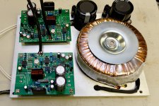
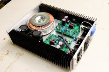
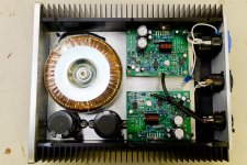
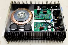
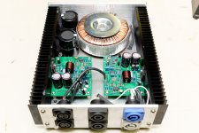
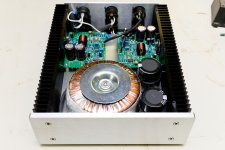
I hope I'm not too late to the Mod-86 2nd birthday party. Here's my contribution.
Cowanaudio,
Fantastic work! I like your direct connections for the signal wiring! When you think about all of Tom's efforts in board layout, etc...minimizing connections (as long as it can be done reliably) is a plus in my opinion. In addition, the simplicity of your power supply with a low impedance buss bar is very well noted. In my build, I paralleled (2) 10,000 uf caps, while wiring them together underneath my PS board for each voltage rail, completely dual mono. I had the space, so I did it, and I had too many PS boards to spare!
<A little off topic> Your website was the reason I went to Earl Geddes' home and listened to his system. The rest is history, my 2 favorite systems are Geddes (and I own the NA12) and Tom Danley's Synergy Horn designs. Thanks again!
Best,
Anand.
Last edited:
So I finished off assembling my two Modulus 86s and did the system check. Everything is within range on U4.
1) -16.5 +16.2
2) -16.5 +16.0
Should I be concerned about the difference between the two?
The DC offset across J1 was below my meter's ability to read. My fluke 12b has a resolution of 1mV. Maybe I can take this to a local meetup and see if I can get a better reading.
Now on to the fun case stuff.
I'm building an all in one enclosure which will include my preamp. My preamp is just a an alps log pot and an input selector. Does anyone have a rotary switch suggestion? I've looked at a lot of grayhills but they all look like messy pinecones to solder. I'd rather have a break out board. Chipamp.com used to have a breakout for a nice selector but I've gathered that that's an unreliable source.
So I finished off assembling my two Modulus 86s and did the system check. Everything is within range on U4.
1) -16.5 +16.2
2) -16.5 +16.0
Should I be concerned about the difference between the two?
Nothing concerning that I see. Mine had differences just as much as yours.
The DC offset across J1 was below my meter's ability to read. My fluke 12b has a resolution of 1mV. Maybe I can take this to a local meetup and see if I can get a better reading.
Let us know, but it is purely academic as the DC offset is soooooo low with the awesome DC servo design!
Now on to the fun case stuff.
I'm building an all in one enclosure which will include my preamp. My preamp is just a an alps log pot and an input selector. Does anyone have a rotary switch suggestion? I've looked at a lot of grayhills but they all look like messy pinecones to solder. I'd rather have a break out board. Chipamp.com used to have a breakout for a nice selector but I've gathered that that's an unreliable source.
Have you looked at Neurochrome's own offerings? 😉 Selector x4
I would replace your entire preamp with this though: Differential Preamp 8×2 😀
Best,
Anand.
Tom how critical is the inductor value? I know the numbers might say 15 turns gives 2.2uH but my experience of winding them is home wound never come close to achieving the expected numbers
Not very. Anything in the 1.0 - 2.5 uH range will work well.
I built the Thiele network as described in the design documentation and measured the impedance of the resulting network on an HP4194A impedance analyzer. I used the "equivalent circuit" function of the analyzer to compute the L and R. The result was within reasonable component tolerances of the spec.
If you don't get the expected inductance, it may be that your inductance meter is using too low of a test frequency. If your meter has an option for using a 100 kHz test signal, I would expect it to be able to measure the inductance of the inductor. Just leave the resistor out during the measurement.
Tom
Last edited:
Please build it straight on spec. Use the BOM.
It is only after that when you could make any sense if requesting something different you'd like it to do.
Build it according to the documentation before tweaking is a good general recommendation for any build.
In case of the Modulus-86, I strongly suggest a "build it according to the documentation and leave it alone" approach. By random component substitutions you are far more likely to cause damage than to make improvements to the performance.
If you really-really-really can't fight the compulsion to tweak, I do provide some general guidelines for component substitutions in Appendix A-2, "Deviations from the Bill-of-Materials (at your own risk)" of the design doc. Should you wish to go down that route and need my help, I will be happy to help. My usual consulting rate will apply. 🙂
The Modulus-86 uses current production parts that are available off the shelf to achieve world-class performance. It has been built successfully by many people across the world. Some have shown their builds here.
Tom
Last edited:
I hope I'm not too late to the Mod-86 2nd birthday party. Here's my contribution.
Hey... Even I was late for my own party... 🙂
That is a super nice and compact build. I really like the false bottom and below deck wiring. I may do exactly that for the li'l desktop amp I'm planning to put together from the SMPS-86 and Modulus-286 prototype I have sitting around.
While you wait for the power switch to arrive, I suggest installing some grommets where the wires go through the false bottom.
It's nice to see people using the speakON and powerCON connectors. I seem to have started a trend. 🙂
Tom
PS: '286' wasn't a typo. You can read more in the Vendor's Bazar.
The DC offset across J1 was below my meter's ability to read. My fluke 12b has a resolution of 1mV.
You're good then. Even I need to use the 6-digit mode on my HP34401A bench top meters when I measure the offset. Using the slow settling helps as well. Measuring uV takes some work.
My preamp is just a an alps log pot and an input selector.
I suggest adding at least a buffer to that. I know some fancy "passive preamps" (= input selector + volume control) but it's really not a good solution from a technical perspective. The variable (and usually highish) output impedance is not a good solution. It sounds like if you add one of my THAT Drivers to what you already have, you'll have a good preamp to drive a Modulus-86.
Does anyone have a rotary switch suggestion?
As Anand said above, my Selector x4 will do the job. It will also provide you with a nice visual indication of which output is selected. The LED of the selected input glows brightly while the un-selected input LEDs glow only subtly. Fun with LEDs... 🙂 The Selector x4 provides signals out that you can use to drive relays for input selection.
Also, as Anand mentioned (thanks for the plug!), my DIFF PRE 8x2 will most certainly meet your preamp needs.
Chipamp.com used to have a breakout for a nice selector but I've gathered that that's an unreliable source.
Judging by the increasing traffic in the "Hello?! Anybody there?" thread and increasing number of paypal disputes reported, I'd agree with your assessment.
Tom
I hope I'm not too late to the Mod-86 2nd birthday party. Here's my contribution.
I'm still waiting for the power switch, it's on the slow boat from China.
What chassis is that?
Looks like a BZxxxx chassis from eBay. It could be one of HiFi2000/ModuShop's chassis as well. For chassis options, check out the DIY Audio store: Chassis – diyAudio Store
They source the ModuShop chassis at very reasonable prices.
Tom
They source the ModuShop chassis at very reasonable prices.
Tom
Hey... Even I was late for my own party... 🙂
That is a super nice and compact build. I really like the false bottom and below deck wiring. I may do exactly that for the li'l desktop amp I'm planning to put together from the SMPS-86 and Modulus-286 prototype I have sitting around.
I think the false bottom worked out well too. It's the first time I've done that on an amp.
While you wait for the power switch to arrive, I suggest installing some grommets where the wires go through the false bottom.
I'm going to change a few things when I pull it down to install the power switch. I wanted to run up the amp into the HP3562A as a proof of concept first.
It's nice to see people using the speakON and powerCON connectors. I seem to have started a trend. 🙂
I've been using SpeakONs since the '90s and the PowerCONs almost as long. I think they are a great connector, never had any problems with them. I did a trial fit of the back panel with bananas and IEC power connectors, but it didn't fit well or look good. The Neutrik connectors were the answer this time.
Last edited:
I built a Mod86 and am about to build a Parallel86 and was concerned about copper wire oxidation.
In an earlier post I asked about the effect of oxidation of copper stranded wire and skin effect as it relates to music.
I got a response saying that skin effect is related to RF or high frequency signals and has no bearing on the audible range we listen to for music.
If that's true why bother with cramolin or Caig products? Why try to make gas tight fittings. Our car, battery acid excluded, and household wiring seem to work for for years. My house wiring is 116 years old and all the lights works.
All the hype seems to be snake oil. Am I missing something?
Dirty or oxidised high resistance connections sound bad. Quality self wiping connectors with high contact pressure avoids problems. I like Neutrik but they are not the only show in town. A poor quality connector could probably have its contact resistance lowered over the long term using products to minimise oxidisation. I'd rather use a quality connector and forget about it.
High quality RF transmission lines and waveguides often use gold or silver plating to reduce loss because nearly all of the current flow is very near to the surface of the conductor. This is a complete non issue for the frequencies, conductor diameters and cable run lengths encountered in audio.
High quality RF transmission lines and waveguides often use gold or silver plating to reduce loss because nearly all of the current flow is very near to the surface of the conductor. This is a complete non issue for the frequencies, conductor diameters and cable run lengths encountered in audio.
- Home
- Amplifiers
- Chip Amps
- Modulus-86 build thread
