They're in Newmarket rather than Ipswich, but yes 🙂
Oh, my bad... 🙂
Thanks Tom - I went to your website and discovered that you'd already sorted this out - duh!
That makes it very simple indeed - sent for the board - many thanks.
Thank you. I just sent you the design doc. Your board will be in the mail by tonight.
Tom
I had to map it. 😉Oh, my bad... 🙂
I am uncertain even if one had a good semiconductor process and freedom of the UK one could do better than THAT. They know audio quite well and presumably have pushed implementation to their process limits---certainly, the noise figure on the 1200 series is up against the Johnson noise limit imposed by the on die feedback resistors. Select slightly different tradeoffs on the efficient frontier imposed by physics, sure. But that's not fundamentally better, just different, though it might be slightly more optimized for any one particular DIY application.
I haven't done the maths but from a glance at the datasheets the same is true or very close to it for a 16x6 at the source end of the interconnect.
I'm not convinced either. Which makes me all the more curious about the fact that Bruno Putzeys dismissed them as having too high distortion. It's below the noise floor of the source, which is good enough for me 🙂
I'd be interested in looking at the specifics if you've a link; didn't find the remarks with a spot of searching.
It does kind of follow, though. nCore is -105dB THD and the 1200 series -106dB THD, so summing the two spectra probably would degrade nCore spec to -102 or -103dB or so.
It does kind of follow, though. nCore is -105dB THD and the 1200 series -106dB THD, so summing the two spectra probably would degrade nCore spec to -102 or -103dB or so.
http://www.hypex.nl/docs/papers/The G Word.pdf
Now when you look at his measurements against the complete Mod-86 this comment causes me some head scratching. But the rest of the article is a good introduction into why balanced is good.
The input stage The input stage is a straight buffer implementing
the improved input biasing network. I would’ve used the Whitlock’s input chips and implemented the capacitive bootstrap technique as well, except that
the distortion performance is not good enough in my view.
Now when you look at his measurements against the complete Mod-86 this comment causes me some head scratching. But the rest of the article is a good introduction into why balanced is good.
I'm not convinced either. Which makes me all the more curious about the fact that Bruno Putzeys dismissed them as having too high distortion. It's below the noise floor of the source, which is good enough for me 🙂
Reading "The G Word", it seems Bruno is mostly miffed that he can't get to use Whitlock's circuit due to THAT's patent claims. I don't see any mention about the THD of the THAT chips in the paper. I haven't read and savoured every word of it, so I could have missed something. I'm pretty sure I haven't, though.
Bruno uses a 2.2 MΩ resistor from Vcm to GND to ensure high common-mode input impedance. Increasing the CM impedance is the right thing to do, but I have seen mention that the megohm resistor to ground causes higher noise than Whitlock's solution. That's probably true, but the noise should be common-mode noise, thus, attenuated by the CMRR. Also, I suspect the majority of the noise issue (assuming there is an issue) can be mitigated by using a source with a low output impedance.
It would be an interesting research project to evaluate the THAT1200 vs Bruno's circuit with resistor tolerances included.
Most of this is firmly in the dBGF level. For those just tuning in, that's dB relative to one metric Gnat Fart. For the MOD86 in its default configuration (20 dB gain), there may be a dB or two of THD+N to gain by reducing the impedances in the THAT1200. That's really quite inconsequential.
For the folks who want higher gain than the default 20 dB, the gain structure could be improved by changing OA1 and OA2 in the THAT1200 to an instrumentation amp front-end. One would either have to convince THAT of the business opportunity and have them change the THAT1200, use Bruno's circuit, or design something else that doesn't infringe on THAT's patents. The end result is guaranteed to be a lot more expensive than a single THAT1200 as it'll require 3-4 audio opamps and at least a quad of precision resistors. One could achieve the same result by putting the extra gain in the preamp. In my DIFF PRE 8x2 that can be accomplished by changing two resistors.
Tom
Yeah, it'd seem that there are bigger fish to fry when your noise and distortion limit in a power amp (before clipping or output current capability limitations, of course) is the line receiver.
Yeah, it'd seem that there are bigger fish to fry when your noise and distortion limit in a power amp (before clipping or output current capability limitations, of course) is the line receiver.
#perspective 🙂
It would be an interesting research project to evaluate the THAT1200 vs Bruno's circuit with resistor tolerances included.
I can post you one if you want/have time to have a measure.
I have a fistful of strong candidates. I just need time in the simulator. I need a few other tasks to get out of the way first. Thanks though.
Tom
Tom
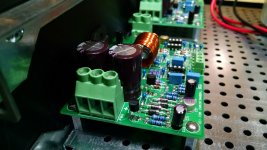
I'm laying out the chassis for a 4 channel Mod 86 in a HiFi2000 / Modushop 2U chassis (from the diyAudio shop) and have hit a small snag. The first photo shows the basic layout, very similar to what Tom did in his builds. The problem is shown in the second photo - with the 3886 sitting in the board but as yet unsoldered and pushed up tight to the heat sink, the standoffs next to the HS fall on the break in the base plate. There's no room for a screw head under the plate.
I can see a couple of solutions. I could lose the base plate and mount directly to the chassis bottom, but that would give up some strength. I could carve out the edge of the plate to make room for the screw while trying to leave enough surface for the screw to bite. Or, could a heat-conductive spacer be used between the 3886 and the HS , say a piece of 1/16" or 1/8" aluminum or copper with conductive grease on both sides? That would make life easy if it wouldn't screw up heat dissipation.
Bill
Attachments

Last edited:
You could attach the standoffs to a piece of 1" x 1/8" aluminum bar using countersunk flat head screws from below then attach the bar to the chassis at the first row of holes.
Although not approved by all Members, in my opinion the PCB support standoffs along the heatsink side can be omitted.
The support at the middle sides stops the PCB tilting in any direction and the 11 leadouts of the chip hold the PCB at a fixed height.
The support at the middle sides stops the PCB tilting in any direction and the 11 leadouts of the chip hold the PCB at a fixed height.
If you opt for the spacer solution, using copper for the shim with aluminum HS might create a galvanic corrosion issue long term - possibly a bad idea even though copper is a better conductor than Al.
For a first approximation, aluminum shim stock will pretty much conduct heat at the same rate as the aluminum heat sink material. There will be some small degradation from a second layer of grease. (assuming most heat compounds are less conductive than Al)
For a first approximation, aluminum shim stock will pretty much conduct heat at the same rate as the aluminum heat sink material. There will be some small degradation from a second layer of grease. (assuming most heat compounds are less conductive than Al)
You could attach the standoffs to a piece of 1" x 1/8" aluminum bar using countersunk flat head screws from below then attach the bar to the chassis at the first row of holes.
Thanks, that might be workable. I'll have to see what I can come up with for aluminum stock.
Although not approved by all Members, in my opinion the PCB support standoffs along the heatsink side can be omitted.
The support at the middle sides stops the PCB tilting in any direction and the 11 leadouts of the chip hold the PCB at a fixed height.
That had occurred to me, but I'd rather mount the board solidly to avoid potential damage in transport. If all comes together I hope it will make it to the next Burning Amp.
Bill
I'm laying out the chassis for a 4 channel Mod 86 in a HiFi2000 / Modushop 2U chassis (from the diyAudio shop) and have hit a small snag.
Small snag aside, it looks pretty good so far.
One curious question: What's the base plate made from? Steel?
Or, could a heat-conductive spacer be used between the 3886 and the HS , say a piece of 1/16" or 1/8" aluminum or copper with conductive grease on both sides? That would make life easy if it wouldn't screw up heat dissipation.
An aluminum head spreader with a light coat of thermal grease on both sides would be the way to go. I'd get a 1" wide piece of 1/8" thick flat bar. Just make sure it's smooth on both sides so you get a good thermal connection.[/QUOTE]
You could attach the standoffs to a piece of 1" x 1/8" aluminum bar using countersunk flat head screws from below then attach the bar to the chassis at the first row of holes.
That'll work too.
Although not approved by all Members, in my opinion the PCB support standoffs along the heatsink side can be omitted.
The support at the middle sides stops the PCB tilting in any direction and the 11 leadouts of the chip hold the PCB at a fixed height.
I'm not a fan of this approach. It sets up the board as a cantilever. Any vibration will causing stress on the LM3886 pins which can lead to failure of the solder joints.
Tom
If all comes together I hope it will make it to the next Burning Amp.
That would be awesome. I'd be curious what people's opinions are.
Tom
FWIW, here's my preferred mounting method.
I cut 1/2" lengths of 1/2" angle aluminum, drilled and tapped for an appropriately sized screw, and mount the board directly to the heat sink. A side benefit to doing it this way is, you can mount the chip and the board to the heat sink before soldering the chip leads to the board, thereby avoiding putting any stress on the chip leads.

Mike
I cut 1/2" lengths of 1/2" angle aluminum, drilled and tapped for an appropriately sized screw, and mount the board directly to the heat sink. A side benefit to doing it this way is, you can mount the chip and the board to the heat sink before soldering the chip leads to the board, thereby avoiding putting any stress on the chip leads.
Mike
Grounding question
I read Bruno's white paper and his diagram on page 9 fig.24 is very interesting. I'm guessing pin1 on most all XLRs has no continuity to anywhere on an XLR.
I know pin1 on my XLR has no continuity to any part of the XLR so a wire is needed, from it to the chassis, to ground the microphone cable shield.
Is there a reason to use pin1? Why not just connect the shield directly to the chassis? Further, why not use an RCA connector with a shielded cable and just connect the shield to the chassis?
I'm a newbie to electronics but the diagram makes me question the need for an XLR.
Hope someone can shed some light.
- Home
- Amplifiers
- Chip Amps
- Modulus-86 build thread