Some weeks ago I read about a study that tried to define wether phase distortion was audible. They used an all-pass to turn the phase at different center frequencies. Test results indicated that phase distortion is audible only with headphones and only at low frequencies up to maybe 2kHz. But the results were barely statistically relevant. So imho it is sufficient to keep phase change below maybe 20 degree in the 100-2000Hz band. However, that only seems relevant in line level equipment and headphone amps, not in power amps.
I would be very much interested in a link to this study.
I would be very much interested in a link to this study.
Human Hearing - Phase Distortion Audibility Part 2 | Audioholics
I'm sorry I didn't attach the source to my first post, I had it bookmarked at work and was at home.
Test results indicated that phase distortion is audible only with headphones and only at low frequencies up to maybe 2kHz. But the results were barely statistically relevant.
Thanks for the link; it might be worth a re-read. Mark's write up doesn't describe Lipshitz's results in quite as much detail as might be desirable but they seem extremely likely to contradict the above, which are Koya's results. Mark goes on to cite Hansen and Madsen, whose results are in clear disagreement with Koya as well.
The ABX findings I have are in agreement with Lipshitz and Hansen and Madsen, though less rigorous due to a smaller cohort and more narrow set of test cases.
Finally my turn to build...
It's finally my turn to build a Modulus-86 Rev. 2.0 amplifier - or at least put one in an enclosure and have a complete product rather than a few boards on a heat sink.
The goal here is to build an amp to drive a pair of LXmini speakers. The amp will need four channels and have the MiniDSP built-in. Some may want to use the Parallel-86 for the woofer, but I chose the Modulus-86 for all channels for simplicity and because I highly doubt I'll ever need more than 40 W to drive the woofer. I'm not trying to rock my house off its foundation after all. 😛
The chassis is a BZ4309 from eBay seller "along1986090". The chassis is $99 with $58 shipping. I bought two of them for a combined total of about $290 including shipping. Now, before you cry FOUL!! consider that just the raw aluminum for each chassis would set you back $78 (Online Metals pricing as of July 11, 2015). This would be a raw aluminum chassis. You'd then have to get it anodized. In short, while $160 is certainly a good chunk of change, it's actually quite a steal for what you get. And, no, I'm not related to the seller. Nor do I get kickbacks... 🙂
The seller shipped via DHL. I ordered on July 1st. The box arrived the 7th of July!
The usable internal dimensions are approximately 330 x 290 x 84 mm. The front is 8 mm thick aluminum. The chassis comes with the power inlet connector (IEC) with fuse holder (5x20 mm). There's a cutout centered on the rear panel for this connector. All screws and threads are metric, which I happen to prefer.
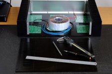
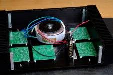
The first image shows the floor plan and mock-up. The second image is after the holes were drilled in the bottom plate. Looks like every thing fits just fine. I made a bracket for the MiniDSP and mounted it vertically. I could probably have squeezed it in on the bottom plate, but I wanted to be able to access the USB port without having to disassemble the chassis completely and wanted the MiniDSP to sit a bit away from the transformer.
I left a gap of about 1 mm between the edge of the board and the heat sink.
Not bad for a few hours' work. Tomorrow I'll attack the front and rear panels.
Tom
It's finally my turn to build a Modulus-86 Rev. 2.0 amplifier - or at least put one in an enclosure and have a complete product rather than a few boards on a heat sink.
The goal here is to build an amp to drive a pair of LXmini speakers. The amp will need four channels and have the MiniDSP built-in. Some may want to use the Parallel-86 for the woofer, but I chose the Modulus-86 for all channels for simplicity and because I highly doubt I'll ever need more than 40 W to drive the woofer. I'm not trying to rock my house off its foundation after all. 😛
The chassis is a BZ4309 from eBay seller "along1986090". The chassis is $99 with $58 shipping. I bought two of them for a combined total of about $290 including shipping. Now, before you cry FOUL!! consider that just the raw aluminum for each chassis would set you back $78 (Online Metals pricing as of July 11, 2015). This would be a raw aluminum chassis. You'd then have to get it anodized. In short, while $160 is certainly a good chunk of change, it's actually quite a steal for what you get. And, no, I'm not related to the seller. Nor do I get kickbacks... 🙂
The seller shipped via DHL. I ordered on July 1st. The box arrived the 7th of July!
The usable internal dimensions are approximately 330 x 290 x 84 mm. The front is 8 mm thick aluminum. The chassis comes with the power inlet connector (IEC) with fuse holder (5x20 mm). There's a cutout centered on the rear panel for this connector. All screws and threads are metric, which I happen to prefer.
The first image shows the floor plan and mock-up. The second image is after the holes were drilled in the bottom plate. Looks like every thing fits just fine. I made a bracket for the MiniDSP and mounted it vertically. I could probably have squeezed it in on the bottom plate, but I wanted to be able to access the USB port without having to disassemble the chassis completely and wanted the MiniDSP to sit a bit away from the transformer.
I left a gap of about 1 mm between the edge of the board and the heat sink.
Not bad for a few hours' work. Tomorrow I'll attack the front and rear panels.
Tom
Attachments
Last edited:
Hi Tom,
Supercool build! I'll be very interested in your impressions of MiniDSP. That looks like the 2x4 K, is that right?
Last month I got a MiniDSP nanoDigi 2x8 B. It's fun to play with, but I don't have all the drivers for my speakers yet. I'll start a thread when I get closer,.. I think my DAC solution will be cool too.
I'm wanting to build 6 modulus86, and need help with a few questions. Is this a good thread for questions?
AlexQS
will one power supply run four modlus boards?
Hi Tomchr,
I am following you build intensely as that's just what i want to do (except i will mount a raspberry pi2 with a TFT touchscreen and a DAC (Sokoris?)
with NAS on the SD card (Volumineo perhaps?)
So ...Will one PSU board service all 4 channels of the Amp?
if so what transformer do you recommend (the V/A would be higher that the original Antek spec for a two channel solution?)
keep em coming😉
regards
Johnny
Supercool build! I'll be very interested in your impressions of MiniDSP. That looks like the 2x4 K, is that right?
Yep. It's the MiniDSP 2x4. If you're building LXmini speakers (as I am) get the MiniDSP from Madisound as part of the LXmini kit. You save about $50 that way.
I'm wanting to build 6 modulus86, and need help with a few questions. Is this a good thread for questions?
I think for the "how do I put this in a box" kinds of questions, this thread would be a good one. For the questions about the Modulus-86, Parallel-86, or Power-86, I suggest using the Modulus-86 thread in the Vendor's Bazaar. For questions that are specific to your situation, you're always welcome to toss me an email through the Contact Us form on my website: www.neurochrome.com
I am following you build intensely as that's just what i want to do (except i will mount a raspberry pi2 with a TFT touchscreen and a DAC (Sokoris?)
with NAS on the SD card (Volumineo perhaps?)
Sounds like quite a project.
So ...Will one PSU board service all 4 channels of the Amp?
Depends... For a two-way stereo setup, such as mine pictured above, one Power-86 board to four Modulus-86 channels should be plenty. That's what I'm planning to use. In the pictures above, you see one Power-86 board and an Antek AN-2222. However, if your plan is to have a four-channel amp driving a surround sound system, you may want to use one Power-86 board per two amp channels to have enough supply capacitance.
Tom
I suppose you will leave out the That chips since they have no role in this setup, no buffer required and MiniDSP output is single ended.
Driveing lx minis
Hi Tom,
Thanks for your reply, I intend to drive lx minis like you, so only one psu for the four amps is good news..should the capicators be updated ( larger values?)
Or will the origional psu cap spec do with respect to driving the lx minis?
Cheers
Johnny
Hi Tom,
Thanks for your reply, I intend to drive lx minis like you, so only one psu for the four amps is good news..should the capicators be updated ( larger values?)
Or will the origional psu cap spec do with respect to driving the lx minis?
Cheers
Johnny
I suppose you will leave out the That chips since they have no role in this setup, no buffer required and MiniDSP output is single ended.
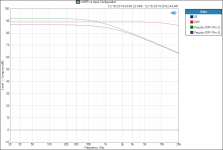
Actually, I'll leave them in. With a pseudo-differential connection to the MiniDSP, I'll still get most of the advantage of the THAT chips.
Attached plot shows the CMRR vs various input configurations.
RED = Differential
PURPLE = Pseudo-Differential
BLUE (line at 0 dB) = Single-Ended
Tom
Attachments
Actually, I'll leave them in. With a pseudo-differential connection to the MiniDSP, I'll still get most of the advantage of the THAT chips.
Attached plot shows the CMRR vs various input configurations.
RED = Differential
PURPLE = Pseudo-Differential
BLUE (line at 0 dB) = Single-Ended
Tom
Actually, that is not correct, there is no advantage to be had from the That chip in this situation, but the good news is that it doesn't matter if you use a MiniDSP.
Balanced connections only make sense in long cable runs, where a common mode signal may develop over the signal wire and its return. For the cable lengths used in home audio, balanced usually isn't necessary because they are too short for significant common mode signals to develop. Within a power amplifier such as you are building, the internal cable runs are even shorter. There will be no appreciable common mode signal developing.
At the same time, nothing comes for free, and so it is with balanced connections. All things being equal, there is at least a 3dB noise penalty because you double the active devices on the input side. However, in this particular case, the noise penalty is even greater because the That is intrinsically a noisier device than LME49710. In addition, the That has more than an order of magnitude greater distortion than the LME. PSRR of the That is 43dB worse than that of the LME, two orders of magnitude. And CMRR of the LME is 30 dB better. In other words, it only pays to have the That included if you get more junk on the line than the That introduces.
Now, none of this fortunately matters because the MiniDSP will swamp all of this as a result of its own distortion, see measurement below. -75dB distortion if you take a friendly look.

If you use a pseudo-balanced connection in the sense it is used in this paper, View attachment balanced.pdf, you will make matters even worse.
Last edited:
Do you have a similar plot for the minidsp 2x8? I hav one of those for 'phase 1' of my active crossover project.
I had a fret for 10 minutes about the THAT chip being the 'worst' part of the mod-86 and then realised, even with it its an order of magnitude better than anything else in my system, so a lot of upgrades would be needed before that became the limiting factor (if ever). Also are you sure on the numbers. A THAT1200 has PSRR of 82dB and noise of -107dBu (ref 0.775V). Yes much worse than the LME, but still not shabby esp when presented with a regulated supply.
I had a fret for 10 minutes about the THAT chip being the 'worst' part of the mod-86 and then realised, even with it its an order of magnitude better than anything else in my system, so a lot of upgrades would be needed before that became the limiting factor (if ever). Also are you sure on the numbers. A THAT1200 has PSRR of 82dB and noise of -107dBu (ref 0.775V). Yes much worse than the LME, but still not shabby esp when presented with a regulated supply.
No, the That is a great part for applications where you need to go balanced, that is not the point. But, it is worse than the LME, which has a PSSR of 125dB. It is all pretty moot given the threshold of audibility, but if extremely low distortion is your game, take the That out when you don't need it.
I don't have the 2x8, so no measurements there. I just know that by translating the curves I develop with the MiniDSP into an analog analog, I can gain 15-20 dB in distortion reduction. I measured my last crossover <-95dB distortion, so that is true 16 bit resolution.
I don't have the 2x8, so no measurements there. I just know that by translating the curves I develop with the MiniDSP into an analog analog, I can gain 15-20 dB in distortion reduction. I measured my last crossover <-95dB distortion, so that is true 16 bit resolution.
I think I will be starting down exactly the same path as you. Where I will finally end up tho is anyones guess!
Sure, but selecting the correct tradeoff requires correct assessment of the junk. The limiting factor here is indeed by far the ADA1701 and related bits in the MiniDSP.In other words, it only pays to have the THAT included if you get more junk on the line than the THAT introduces.
You appear to be assuming the voltage developed by a power amp pulling several amps through a supply impedance of tens or hundreds of milliohms does not introduce a significant offset between amplifier local ground and source ground in the case where source and amp share a secondary. Given MiniDSP output levels this implies an SnR around 0dB is acceptable. Most would consider such a low SnR unacceptable. Certainly it's well above -75dB error terms from the MiniDSP claimed as the limiting factor, implying O(80+dB) CMRR is required at the power amp input.Actually, that is not correct, there is no advantage to be had from the THAT chip in this situation.
Yup. However the 120x series' -106 dB THD+N doesn't become significant until SnR approaches the same level. So this consideration is not relevant to the proposed unbalanced topology unless supply impedances can be reduced to nanoOhms. Considering a single square of one ounce copper on a PCB is around 500 microOhms this is pretty much impossible.the THAT has more than an order of magnitude greater distortion than the LME
You appear to be assuming unregulated operation, which is incorrect as the Mod has onboard regulators. Once reworked to correct this error, the maths underlying this line of argument won't hold---the nV error residuals from PSRR are well below the uV noise floor.PSRR of the THAT is 43dB worse than that of the LME, two orders of magnitude.
Actually, the THAT 1200 is at least 40nV RMS quieter than a 49710 based equivalent. Typical audio band noise in an LME49710 difference amplifier implemented with the 6k feedback impedances used on the THAT 1200 is -107 dBu. This is 1dBu lower than -106 dBu THAT specifies for the 1200, leaving about 420nV RMS for the input buffers in the equivalent three op amp instrumentation amplifier topology. Used as a unity strapped buffer, the 49710 is not quite capable of this. Note the noise contribution of the servo amplifier and its match quad of resistors is neglected here.However, in this particular case, the noise penalty is even greater because the THAT is intrinsically a noisier device than LME49710.
You also may wish to refer to texts such as a Analog's Instrumentation Amplifiers Guide for a deeper understanding of how the three op amp instrumentation amplifier. Depending on the amount spent on resistor matching, CMRR of the 49710 equivalent will be 10 to 50 dB lower than the THAT 120x. Not 30dB higher as asserted---the device CMRR controls the error from the frontend buffers whilst resistor tolerances dominate difference amplifier error.
I assume you're referring to the unbalanced output figure on page 1, which shows the poor practice of earthing only one end of the shield. This has not, to my knowledge, ever been recommended on any of the Modulus-86 threads. So, while this somewhat vague assertion is likely correct, it is not a relevant concern.If you use a pseudo-balanced connection in the sense it is used in this paper, View attachment 493350, you will make matters even worse.
Last edited:
Academically, you're right. Practically though...Balanced connections only make sense in long cable runs, where a common mode signal may develop over the signal wire and its return. For the cable lengths used in home audio, balanced usually isn't necessary because they are too short for significant common mode signals to develop. Within a power amplifier such as you are building, the internal cable runs are even shorter. There will be no appreciable common mode signal developing.
In an extreme case, suppose you plug your signal source and your amp into two different outlets, which are fed from two different breakers in the panel on opposite AC phases. And you've got a bunch of other stuff plugged into each circuit, all with Y capacitors which are inducing currents between hot and the ground, in opposite directions.
Now assume the RCAs on both source and amp are connected to chassis ground. You've just created two things: (1) a great big loop antenna in your house's electrical wiring. Amp ground -> circuit #1 -> panel -> circuit #2 -> DAC -> amp ground again. This is probably going to pick up AM radio, 160/80/40m ham radio, LORAN and who knows whatever HF trash happens to be in the air. And (2), you're creating a secondary path for the aforementioned Y capacitor current to flow through. Currents from both of these sources is going to excite some voltage across your interconnections, which the unbalanced input on your amp will offer zero CMRR to correct.
Even in something as small as this amp, unbalanced ground connections between the MiniDSP and amp ground could start carrying power currents and create trouble. If you've got fat grounds between MiniDSP/amp and amp/PSU, and a thin wire between MiniDSP and PSU, where's the MiniDSP going to return its power supply current through?
Breaking all these extra ground paths is of great benefit. Balanced audio inputs allow that.
Sure, but selecting the correct tradeoff requires correct assessment of the junk. The limiting factor here is indeed by far the ADA1701 and related bits in the MiniDSP.
Yes, that is what I said. You need a better source for this to become relevant.
You appear to be assuming the voltage developed by a power amp pulling several amps through a supply impedance of tens or hundreds of milliohms does not introduce a significant offset between amplifier local ground and source ground in the case where source and amp share a secondary. Given MiniDSP output levels this implies an SnR around 0dB is acceptable. Most would consider such a low SnR unacceptable. Certainly it's well above -75dB error terms from the MiniDSP claimed as the limiting factor, implying O(80+dB) CMRR is required at the power amp input.
Grounding is always the biatch in situations like this. To zoom in on this particular situation, it would be bad practice to take the speaker grounds from the LM3886 boards. Speaker grounds should be tied to a star ground as close as possible to the PSU. As soon as you are thinking about amplifier local ground and source ground, you have made a serious mistake in the grounding lay out. Sorry, I can't figure out what you mean by "Given MiniDSP....power input."
Yup. However the 120x series' -106 dB THD+N doesn't become significant until SnR approaches the same level. So this consideration is not relevant to the proposed unbalanced topology unless supply impedances can be reduced to nanoOhms. Considering a single square of one ounce copper on a PCB is around 500 microOhms this is pretty much impossible.
-106 dBu is the noise figure for the That, and coincidentally, the THD figure is also -106 dB, so I would assume THD+N is around -103dB. This is very good. But why would you cascade it with the LME if you don't need it. On a separate note, signals below the noise floor are audible, which is why THD+N figures aren't really that relevant.
You appear to be assuming unregulated operation, which is incorrect as the Mod has onboard regulators. Once reworked to correct this error, the maths underlying this line of argument won't hold---the nV error residuals from PSRR are well below the uV noise floor.
Sure, but noise sources do add up, so get rid of them when you don't need them.
Actually, the THAT 1200 is at least 40nV RMS quieter than a 49710 based equivalent. Typical audio band noise in an LME49710 difference amplifier implemented with the 6k feedback impedances used on the THAT 1200 is -107 dBu. This is 1dBu lower than -106 dBu THAT specifies for the 1200, leaving about 420nV RMS for the input buffers in the equivalent three op amp instrumentation amplifier topology. Used as a unity strapped buffer, the 49710 is not quite capable of this. Note the noise contribution of the servo amplifier and its match quad of resistors is neglected here.
This is not what I stated. A That as an instrumentation amp may be quieter than an LME4910 in a comparable situation, but in this implementation, the LME is not used in such role. The noise addition of the That, low as it may be, is unnecessary in this situation. I guestimate it worsens the noise figure with about 3 dB.
You also may wish to refer to texts such as a Analog's Instrumentation Amplifiers Guide for a deeper understanding of how the three op amp instrumentation amplifier. Depending on the amount spent on resistor matching, CMRR of the 49710 equivalent will be 10 to 50 dB lower than the THAT 120x. Not 30dB higher as asserted---the device CMRR controls the error from the frontend buffers whilst resistor tolerances dominate difference amplifier error.
We are talking about CMRR in two different meanings here. First, we are not using the LME as an instrumentation amp. The CMRR which is relevant here is the immunity against voltage swing of the + and - input in a non-inverting configuration. LME is 30 dB better in this respect. But I agree I made an apple and pears comparison. The point is that a balanced connection between the MiniDSP and the Modulus-86 is unnecessary. Leaving out an unnecessary component that is in series with the rest is always better, however good that superfluous component is.
I assume you're referring to the unbalanced output figure on page 1, which shows the poor practice of earthing only one end of the shield. This has not, to my knowledge, ever been recommended on any of the Modulus-86 threads. So, while this somewhat vague assertion is likely correct, it is not a relevant concern.
No, Tom spoke about a pseudo- or quasi balanced connection between the MiniDSP and the Modulus-86. This requires inverting the MiniDSP signal, putting yet another opamp in the chain.
Last edited:
Separate secondaries are seldom that extreme of a case due to green wire providing a somewhat stable voltage reference (class I devices) or ground synchronization through the interconnect shield (class II)---more about that over in the Mod vendor thread. Shared secondary, as in the case of the LXmini build here, is usually requiring higher CMRR as each individual channel's ground bounces relative to the common centre tap of the secondaries.In an extreme case...
That's not actually the case (and typically that's not what's meant by pseudodifferential interconnect). The relevant diagrams are in the Mod vendor's thread but aren't popping for me in a search. They're the same as the first figure in section 4.5 here though (page 4). So long as the common mode input impedance is high enough the unbalanced source impedance isn't an issue.This requires inverting the MiniDSP signal, putting yet another opamp in the chain.
Then you're back to the problem of insufficient CMRR for the other considerations to be relevant.First, we are not using the LME as an instrumentation amp.
Looks like you'll want to work through the unbalanced SnR maths then. It's pretty basic, really; a typical 1mW home audio listening power is about 1.6mV input to the Mod. Each channel pulls around 65mA when operating within the 3886 bias so, if the bridge diode conduction angle is around 15 degrees idling, then a supply impedance around 25 mOhm will yield somewhere around 0dB SnR due to the bounce delivered over it. This is lower than the 35 mOhm or so found in earlier discussion in the Mod vendor's forum thread but the wiring harness here is a bit more compact.I can't figure out what you mean by "Given MiniDSP....power input."
One can elaborate on this as one wishes; intro to the maths here.
Last edited:
No, Tom spoke about a pseudo- or quasi balanced connection between the MiniDSP and the Modulus-86. This requires inverting the MiniDSP signal, putting yet another opamp in the chain.
What Tom means is twisted pair with shield. Shield and -ve connected at single ended end and normal balanced connection at other end. No extra opamps required.
- Home
- Amplifiers
- Chip Amps
- Modulus-86 build thread